
User's Manual


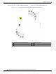
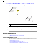
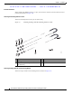


Table Of Contents
- Contents
- Preface
- Overview
- Installation
- Preparing for Installation
- Unpacking the Components
- Installation Guidelines
- Installing the Devices
- Connecting the Protective Ground and Power
- Wiring the Alarm Circuits
- Connecting to Device Ports

29/OCT/2014 REVIEW DRAFT — CISCO CONFIDENTIAL
2-19
Cisco IR500 Series WPAN Gateway and Range Extender Installation and Configuration Guide
Chapter 2 Installation
Connecting the Protective Ground and Power
Figure 2-9 Crimping the Ring Terminal
76666
Step 4 Slide the ground screw through the terminal.
Step 5 Insert the ground screw into the functional ground screw opening on the right side panel.
Step 6 Use a ratcheting torque screwdriver to tighten the ground screw and ring terminal to the WPAN gateway
side panel to 3.5 in-lb (0.4 N-m). The torque should not exceed 3.5 in-lb (0.4 N-m). See Figure 2-10.
Figure 2-10 Installing the Ground-Lug Screw
391917
1
1 Ground cable