
User's Manual


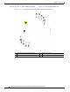
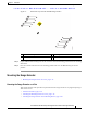
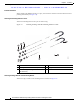


Table Of Contents
- Contents
- Preface
- Overview
- Installation
- Preparing for Installation
- Unpacking the Components
- Installation Guidelines
- Installing the Devices
- Connecting the Protective Ground and Power
- Wiring the Alarm Circuits
- Connecting to Device Ports

29/OCT/2014 REVIEW DRAFT — CISCO CONFIDENTIAL
2-20
Cisco IR500 Series WPAN Gateway and Range Extender Installation and Configuration Guide
Chapter 2 Installation
Connecting the Protective Ground and Power
Step 7 Attach the other end of the ground wire to a grounded bare metal surface, such as a ground bus, a
grounded DIN rail, or a grounded bare rack.
Wiring the WPAN Gateway DC Power
Warning
When you connect or disconnect the power and/or alarm connector with power applied, an electrical
arc can occur. This could cause an explosion in hazardous area installations. Be sure that all power
is removed from the switch and any other circuits. Be sure that power cannot be accidentally turned
on or verify that the area is nonhazardous before proceeding.
Statement 1058
Warning
Explosion Hazard—The area must be known to be nonhazardous before installing, servicing, or
replacing the unit.
Statement 1082
Warning
Explosion Hazard—Substitution of components may impair suitability for Class I, Division 2/Zone 2.
Statement 1083
To wire the WPAN Gateway to a DC power source:
Step 1 Locate the power and alarm connector on the WPAN gateway front panel (see Figure 2-11).
Figure 2-11 WPAN Gateway Power and Alarm Connector
391216
Step 2 Identify the connector positive and return DC power connections. The labels for the power and alarm
connector are shown in Table 2-1.