
User's Manual
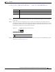
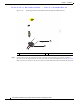
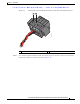
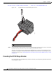


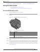
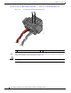
Table Of Contents
- Contents
- Preface
- Overview
- Installation
- Preparing for Installation
- Unpacking the Components
- Installation Guidelines
- Installing the Devices
- Connecting the Protective Ground and Power
- Wiring the Alarm Circuits
- Connecting to Device Ports

29/OCT/2014 REVIEW DRAFT — CISCO CONFIDENTIAL
2-22
Cisco IR500 Series WPAN Gateway and Range Extender Installation and Configuration Guide
Chapter 2 Installation
Connecting the Protective Ground and Power
Figure 2-13 Removing the Power and Alarm Connector from the WPAN Gateway
1
391221
2
1 Power and alarm connector Power and alarm connector connection
Step 6 On the power and alarm connector, insert the exposed part of the positive wire into the connection
labeled "V" and the exposed part of the return wire into the connection labeled "RT". See Figure 2-14.
Make sure
that you cannot see any wire lead. Only wire with insulation should extend from the connector