
User's Manual
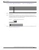
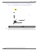
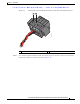
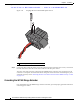


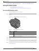
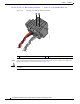
Table Of Contents
- Contents
- Preface
- Overview
- Installation
- Preparing for Installation
- Unpacking the Components
- Installation Guidelines
- Installing the Devices
- Connecting the Protective Ground and Power
- Wiring the Alarm Circuits
- Connecting to Device Ports

29/OCT/2014 REVIEW DRAFT — CISCO CONFIDENTIAL
2-29
Cisco IR500 Series WPAN Gateway and Range Extender Installation and Configuration Guide
Chapter 2 Installation
Wiring the Alarm Circuits
Wiring the Alarm Circuits
• Wiring the WPAN Gateway Alarm, page 2-29
• Attaching the Power and Alarm Connector to the WPAN Gateway, page 2-31
Wiring the WPAN Gateway Alarm
To connect the WPAN gateway alarm connections:
Step 1 Note the alarm connections as described in Figure 2-20. The alarm connection labels are described in
Table 2-2.
Figure 2-20 WPAN Gateway Power and Alarm Connector
391216
Ta b le 2-2 Power and Alarm Connector Labels
Label Description
V Positive DC power connection
RT Return
A Each alarm connection is labeled identicall
y—this means each
connection can be an
‘Alarm in’ or ‘Alarm reference’ signal, provided the second alarm connection
provides the other alarm signal.
Step 2 Measure two strands of twisted-pair wire (18-to-20 AWG) long enough to connect to the external alarm
device.
Step 3 Use a wire stripper to remove the casing from both ends of each wire to 0.25 inch (6.3 mm) ± 0.02 inch
(0.5 mm). Do not strip more than 0.27 inch (6.8 mm) of insulation from the wires. Stripping more than
the recommended amount of wire can leave exposed wire from the alarm connector after installation.
Step 4 Insert the exposed wires for the external alarm device into the power and alarm connector connections
as shown in Figure 2-21.