
User's Manual
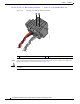
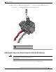

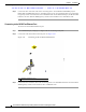

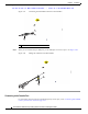

Table Of Contents
- Contents
- Preface
- Overview
- Installation
- Preparing for Installation
- Unpacking the Components
- Installation Guidelines
- Installing the Devices
- Connecting the Protective Ground and Power
- Wiring the Alarm Circuits
- Connecting to Device Ports

29/OCT/2014 REVIEW DRAFT — CISCO CONFIDENTIAL
2-32
Cisco IR500 Series WPAN Gateway and Range Extender Installation and Configuration Guide
Chapter 2 Installation
Wiring the Alarm Circuits
Step 1 Insert the power and alarm connector into the receptacle on the WPAN gateway front panel. See
Figure 2-23.
Figure 2-23 Connecting the Power and Alarm Connector to the WPAN Gateway
391222
1
1 Power and alarm connector captive right side screw
Step 2 Use a ratcheting torque flathead screwdriver to tighten the captive screws on both sides of the power and
alarm connector to 2 in-lb (0.23 N-m).
Caution Do not over-torque the power and alarm connector's captive screws. The torque should not exceed 2 in-lb
(0.23 N-m).