
Installation Instructions Chapter 2a


Navini Networks, Inc. Ripwave Base Station I&C Guide
Chapter 2a
Part #40-00047-02 Rev F v1.0 (1.20) 43
October 9, 2003
Network Architecture Plan
The IP Networking community involved in the project, both from Navini and the customer, often
work together to analyze and plan how the Ripwave system will be integrated into the
customer’s network. Of course, they are looking for efficient operation of the system and
seamless integration. They have to plan the traffic routing, IP addressing, protocol compatibility,
and so forth.
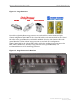
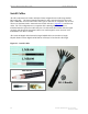
Antenna Power & Cable Selection
The size and type of cable used to install the Base Station affect power loss and calibration range
for the transmitter and receiver. It is at this point in the process that the specific cable
manufacturer, type of cable, and cable size must be determined. A complete procedure and tool
are explained in Appendix L. Refer, also, to Chapter 1, Page 8 “Regulatory Information” for
FCC warning regarding RF, and UL and NEC/CEC information regarding cable length and
connectors. All BTS and RF shelf Coax and Digital cables between the Digital and RF Shelves
are 60 inches in length. Physical distance between Digital and RF Shelves will always be less
than the cable length.
Bill of Materials
The customer has to generate the Bill of Materials (BoM) - the actual equipment order to be
manufactured and shipped to the installation site. Navini can provide part numbers and ordering
information, as well as recommendations and other details that will assist customers in the
correct placement of orders. There is a sample Bill of Materials in Appendix M.
Acquire Materials
Once ordered, the customer ensures that everything required for installing the Base Station is
secured and at the deployment site.
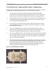
Confirm Backhaul Connection, EMS Server & FTP Server, Input
Power & Grounding at Site
The Backhaul connection for the Ripwave Base Station consists of up to two (2) Ethernet cable
connections with RJ-45 connectors for each BTS installed, OR, up to eight (8) T1 connections
with RJ-48 connectors for each BTS. The quantity of each connection will depend on the site
requirements. These connections need to be made available before installation begins. Refer to
the Regulatory Information in Chapter 1, Page 8 regarding backhaul connections, power and
grounding.