
Installation Instructions Chapter 2a

Navini Networks, Inc. Ripwave Base Station I&C Guide
Chapter 2a
Part #40-00047-02 Rev F v1.0 (1.20) 45
October 9, 2003
Install Power & Grounding
Check all regulatory standards (refer to Chapter 1, Page 8 “Regulatory Information”) prior to
installation.
System Ground Buss Bar & Surge Protectors
The Base Station system ground buss bar and data/power cable surge protectors are mounted on
the wall adjacent to the BTS rack or enclosure. They should be mounted per accepted telecom
standards and procedures.
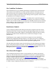
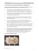
Step 1. Mount the data/power cable surge protectors (Figure 10) with the label ‘lines’ toward
the RFS and the label ‘BTS’ toward the BTS.
Step 2. Apply a thin coat of anti-oxidant joint compound to both sides of the system ground
buss bar to ensure proper connection between it and the surge protectors.
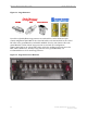
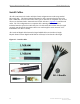
Figure 10: Data/Power Cable Surge Protector (Not Needed in TTA BTS)
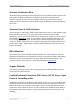
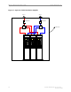
To install the eight (8) antenna and one (1) cal cable surge protectors (Figure 11), and the one (1)
or two (2) Global Positioning System (GPS) surge protectors (Figure 11) in the system ground
buss bar, follow the steps below.
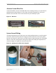
1. Install the rubber gasket into the groove in the surge protector.
2. Install the surge protector in the system ground buss bar with the surge side toward the
antenna and the protected side toward the BTS.
3. Install the star washer and nut on the top of the surge protector. Torque the nut to 140-150
inch-pounds.
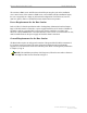
4. When finished, the mounted surge protectors in the buss bar will appear as in Figure 12.