
Installation Instructions Chapter 2b

Navini Networks, Inc. Ripwave Base Station I&C Guide
Chapter 2b
Part #40-00047-03 Rev F v1.0 (TTA) 57
October 23, 2003
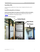
Connect Input Power
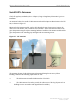
Next, connect the power supply to the BTS card cage (Figure 24). The gauge of the wire is
determined by the length of the run and by NEC/CEC standards (refer to Chapter 1, Page 8
“Regulatory Information”). Use a 60-amp circuit breaker when running the line. Terminate both
of the input power wires and the ground wire with a ¼- inch terminal lug. Assuming a +24 VDC
power supply, connect the +24 VDC input power connections and the +24 VDC return wires to
the BTS card cage.
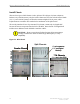
WARNING! Ensure that the power is off before connecting the input power wires to the
BTS input terminals.
If the input power is 120 VAC, plug the two power-supply input cables into 120 VAC outlets,
and turn on the circuit breaker on the power supply. If the input power is 24 VDC, check for +24
VDC across the input terminals of the BTS card cage. If +24 VDC is not present across the input
terminals, check all input power wiring for proper connections. Also, check the power supply for
proper operation and the fuses for continuity.
When finished, turn off the power supply.
Figure 24: Split Chassis Power Connections
BTS +24 VDC Input Terminals
Ground Lug
BTS +24 VDC Input Terminals
Ground Lug