
Installation Instructions Chapter 2b

Navini Networks, Inc. Ripwave Base Station I&C Guide
Chapter 2b
Part #40-00047-03 Rev F v1.0 (TTA) 59
October 23, 2003
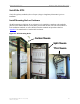
Connect BTS to Ground Connections
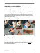
All connections need to be checked before power is applied to the system. At a minimum,
perform the following:
?? Ensure continuity across all ground connections.
?? Ensure an open connection from the power supply output (positive input to the BTS card
cage) to frame ground.
Check all regulatory standards (Chapter 1, Page 8 “Regulatory Information”) related to power
and grounding. All power and ground conductors must be mechanically supported to avoid strain
of the wires and connection points.
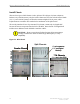
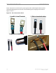
Figure 26: Preparing Power and Grounding Connector Tips
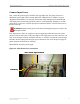
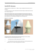
Connect Chassis Alarms
The chassis contains two connectors that are used to send alarm indications to the BTS when the
BTS is housed in an outdoor enclosure. One of the connectors, labeled “CABINET ALARM”, is
used to trigger alarm conditions that occur within the external chassis. The second connector,
labeled “BBU”, is used to process alarms from a battery backup unit. Refer to Appendix P for
instructions on connecting the alarms.