
Installation Instructions Chapter 2d

Navini Networks, Inc. Ripwave Base Station I&C Guide
Chapter 2d
Part #40-00047-05 Rev F v1.0 (TTA) 65
October 23, 2003
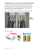
The RFS has ten cable connectors on the bottom of the unit. Eight are antenna connections, with
the connectors alternately numbered from right to left as shown in Figure 33. The two connectors
in the middle are for antenna calibration and data/DC power connections. Install surge protectors
on nine (9) of the RFS connectors – the eight antenna connectors and the calibration connector.
The surge protectors must be installed directly to the RFS to provide protection for the antenna
elements. Torque the surge protectors to 20-24 inch-pounds.
Figure 33: PolyPhaser PSX-ME Surge Protectors at the Antenna (RF and Cal Cables)
Figure 34: Surge Protectors
PSX-ME PSX DGXZ+06NFNF-A
3406.17.0012 3406.17.0009
PSX-MEPSX-ME PSXPSX DGXZ+06NFNF-A
3406.17.00123406.17.0012 3406.17.00093406.17.0009
6 2 5 18 4 7 3
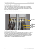
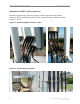
Surge
Protectors
6 2 5 18 4 7 3
Surge
Protectors