
Specifications Chapter 2c

Navini Networks, Inc. Ripwave Base Station I&C Guide
Chapter 2c
Part #40-00047-04 Rev F v1.0 (TTA) 61
October 23, 2003
Install the RFS
Check all regulatory standards (refer to Chapter 1, Page 8 “Regulatory Information”) prior to
installation. Now that the BTS is in place, the RFS is readied for installation. Follow the Panel or
Omni Antenna information and procedures below. Reference the specifications in Appendix H.
Panel Antenna
The RFS Panel antenna is installed on a structure, such as a tower or a pole, which is defined in
the site survey and design. Following are the steps to complete the installation of the panel
antenna.
Verify RFS Operation
Verify proper operation of the RFS before installation. Test the transmit and receive path of each
antenna in the RFS per Appendix S, and using the RFS System Test Form in Appendix O.
Set the Downtilt
Check the engineering study for the required downtilt of the antenna. The panel antenna has 6
o
of
fixed electrical downtilt but it can be mechanically adjusted for an uptilt of 0 to 10
o
. As a result,
the main lobe of the beam can be pointed between 4 degrees above and 6 degrees below the
horizon.
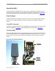
Figure 28: Panel Antenna Elements
Weatherized
connectors
Mounting
Bracket
(downtilt
adjustment)
Weatherized
connectors
Mounting
Bracket
(downtilt
adjustment)