
Specifications Chapter 2c

Ripwave Base Station I&C Guide Navini Networks, Inc.
Chapter 2c
64 Part #40-00047-04 Rev F v1.0 (TTA)
October 23, 2003
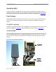
Verify the Downtilt
Using an inclinometer (Figure 32), check the downtilt of the RFS antenna. If required, adjust the
angle using the downtilt adjustment brackets. Be sure to include any electrical uptilt or downtilt
built into the antenna in the setting.
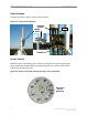
Tighten the mounting hardware to secure the RFS in the proper position. Recheck the downtilt
angle again to verify proper position. Repeat the procedure for all other antennas that are
installed in the system. Ensure that they are mounted in the proper direction and with the correct
downtilt angle.
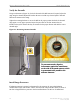
Figure 32: Measuring Antenna Downtilt
Install Surge Protectors
If lightning protection is required, as determined by the customer, the power/data lightning
arrestors must comply with UL497. Cables, such as the RF and power/data cables, in excess of
140 feet in length must have protective devices installed that are UL497A or UL497B listed.
For accurate results, align the
inclinometer against the metal frame
on the side of the panel antenna, which
is guaranteed to be parallel to the
antenna elements
For accurate results, align the
inclinometer against the metal frame
on the side of the panel antenna, which
is guaranteed to be parallel to the
antenna elements