Cisco ME 2400 Ethernet Access Switch Hardware Installation Guide November 2005 Corporate Headquarters Cisco Systems, Inc. 170 West Tasman Drive San Jose, CA 95134-1706 USA http://www.cisco.
THE SPECIFICATIONS AND INFORMATION REGARDING THE PRODUCTS IN THIS MANUAL ARE SUBJECT TO CHANGE WITHOUT NOTICE. ALL STATEMENTS, INFORMATION, AND RECOMMENDATIONS IN THIS MANUAL ARE BELIEVED TO BE ACCURATE BUT ARE PRESENTED WITHOUT WARRANTY OF ANY KIND, EXPRESS OR IMPLIED. USERS MUST TAKE FULL RESPONSIBILITY FOR THEIR APPLICATION OF ANY PRODUCTS.
C O N T E N T S Preface vii Audience Purpose vii vii Organization vii Conventions viii Related Publications xiii Obtaining Documentation xiv Cisco.
Contents Rear Panel Description 1-6 Power Connectors 1-7 Cisco ME AC Switch Power Supply Cisco ME DC Switch Power Supply Console Port 1-7 Management Options 1-7 Network Configurations CHAPTER 2 Switch Installation 1-7 1-7 1-8 2-1 Preparing for Installation 2-1 Warnings 2-1 Installation Guidelines 2-4 Verifying Package Contents 2-6 Verifying Switch Operation 2-7 Powering Off the Switch 2-7 Installing the Switch 2-7 Rack-Mounting 2-7 Removing Screws from the Switch 2-8 Attaching Brackets to the Swit
Contents APPENDIX A Technical Specifications APPENDIX B Connector and Cable Specifications A-1 B-1 Connector Specifications B-1 10/100 Ports B-1 SFP Module Ports B-2 Console Port B-3 Cable and Adapter Specifications B-3 Two Twisted-Pair Cable Pinouts B-3 Four Twisted-Pair Cable Pinouts for 1000BASE-T Ports Crossover Cable and Adapter Pinouts B-5 Identifying a Crossover Cable B-5 Adapter Pinouts B-5 APPENDIX C Connecting to DC Power Preparing for Installation C-1 C-1 Grounding the Switch C-2 Pr
Contents Cisco ME 2400 Ethernet Access Switch Hardware Installation Guide vi OL-7678-01
Preface Audience This guide is for the networking or computer technician responsible for installing the Cisco Metro Ethernet (ME) 2400 Series Ethernet Access switch, hereafter known as the switch. We assume that you are familiar with the concepts and terminology of Ethernet and local area networking. Purpose This guide describes the hardware features of the Cisco ME switch.
Preface Conventions Appendix B, “Connector and Cable Specifications,” describes the connectors, cables, and adapters that can be used to connect to the switch. Appendix C, “Connecting to DC Power”describes how to connect the Cisco ME switch to a direct current (DC)-input power source. Appendix D, “Configuring the Switch with the CLI-Based Setup Program,” has an installation and setup procedure for a standalone switch.
Preface Conventions Varoitus TÄRKEITÄ TURVALLISUUSOHJEITA Tämä varoitusmerkki merkitsee vaaraa. Tilanne voi aiheuttaa ruumiillisia vammoja. Ennen kuin käsittelet laitteistoa, huomioi sähköpiirien käsittelemiseen liittyvät riskit ja tutustu onnettomuuksien yleisiin ehkäisytapoihin. Turvallisuusvaroitusten käännökset löytyvät laitteen mukana toimitettujen käännettyjen turvallisuusvaroitusten joukosta varoitusten lopussa näkyvien lausuntonumeroiden avulla.
Preface Conventions Aviso INSTRUÇÕES IMPORTANTES DE SEGURANÇA Este símbolo de aviso significa perigo. Você está em uma situação que poderá ser causadora de lesões corporais. Antes de iniciar a utilização de qualquer equipamento, tenha conhecimento dos perigos envolvidos no manuseio de circuitos elétricos e familiarize-se com as práticas habituais de prevenção de acidentes.
Preface Conventions Aviso INSTRUÇÕES IMPORTANTES DE SEGURANÇA Este símbolo de aviso significa perigo. Você se encontra em uma situação em que há risco de lesões corporais. Antes de trabalhar com qualquer equipamento, esteja ciente dos riscos que envolvem os circuitos elétricos e familiarize-se com as práticas padrão de prevenção de acidentes. Use o número da declaração fornecido ao final de cada aviso para localizar sua tradução nos avisos de segurança traduzidos que acompanham o dispositivo.
Preface Conventions Cisco ME 2400 Ethernet Access Switch Hardware Installation Guide xii OL-7678-01
Preface Related Publications Related Publications You can order printed copies of documents with a DOC-xxxxxx= number. For more information, see the “Obtaining Documentation” section on page xiv. These documents provide complete information about the switch and are available from this Cisco.com site: http://www.cisco.com/univercd/cc/td/doc/product/metro/me2400/index.
Preface Obtaining Documentation • Cisco ME 2400 Ethernet Access Switch Command Reference (order number DOC-78-78-17061=). This reference provides detailed descriptions of the Cisco IOS commands specifically created or modified for the switch. • Cisco Metro Ethernet 2400 Ethernet Access Switch System Message Guide (order number DOC-78-17063-=). This guide provides descriptions of the system messages specifically created or modified for the switch.
Preface Documentation Feedback The Product Documentation DVD is available as a single unit or as a subscription. Registered Cisco.com users (Cisco direct customers) can order a Product Documentation DVD (product number DOC-DOCDVD=) from Cisco Marketplace at this URL: http://www.cisco.com/go/marketplace/ Ordering Documentation Beginning June 30, 2005, registered Cisco.com users may order Cisco documentation at the Product Documentation Store in the Cisco Marketplace at this URL: http://www.cisco.
Preface Obtaining Technical Assistance Reporting Security Problems in Cisco Products Cisco is committed to delivering secure products. We test our products internally before we release them, and we strive to correct all vulnerabilities quickly. If you think that you might have identified a vulnerability in a Cisco product, contact PSIRT: • Emergencies — security-alert@cisco.
Preface Obtaining Technical Assistance Note Use the Cisco Product Identification (CPI) tool to locate your product serial number before submitting a web or phone request for service. You can access the CPI tool from the Cisco Technical Support & Documentation website by clicking the Tools & Resources link under Documentation & Tools. Choose Cisco Product Identification Tool from the Alphabetical Index drop-down list, or click the Cisco Product Identification Tool link under Alerts & RMAs.
Preface Obtaining Additional Publications and Information Obtaining Additional Publications and Information Information about Cisco products, technologies, and network solutions is available from various online and printed sources. • Cisco Marketplace provides a variety of Cisco books, reference guides, documentation, and logo merchandise. Visit Cisco Marketplace, the company store, at this URL: http://www.cisco.
C H A P T E R 1 Product Overview The Cisco Metro Ethernet (ME) 2400 Ethernet Access switch—also referred to as the switch—is an Ethernet access switch to which you can connect other network devices such as routers, other switches, a home access gateway (HAG), or a computer. This chapter provides a functional overview of the Cisco ME switch.
Chapter 1 Product Overview Front Panel Description – 100BASE-LX – 1000BASE-BX – 1000BASE-LX/LH – 1000BASE-SX – 1000BASE-T – 1000BASE-ZX – Coarse wavelength-division multiplexing (CWDM) Note When installed in Cisco ME switches, 1000BASE-T SFP modules can operate at 10, 100, or 1000 Mbps in full-duplex mode or at 10 or 100 Mbps in half-duplex mode. Note By default, the SFP module ports on the Cisco ME switch are configured as network node interfaces (NNIs).
Chapter 1 Product Overview Front Panel Description Front Panel Descriptions The 10/100 Fast Ethernet ports on the switch are grouped in pairs. The first member of the pair (port 1) is above the second member (port 2) on the left. Port 3 is above port 4, and so on, as shown in Figure 1-1 (the Cisco ME AC switch) and Figure 1-2 (the Cisco ME DC switch). The SFP module slots are numbered 1 and 2. Cisco ME 2400 AC Ethernet Access Switch Front Panel 1 SYSTEM 2 3 1X RATING 100 1A-0.
Chapter 1 Product Overview Front Panel Description When set for autonegotiation, the port senses the speed and duplex settings of the attached device and advertises its own capabilities. If the connected device also supports autonegotiation, the switch port negotiates the best connection (the fastest line speed that both devices support and full-duplex transmission if the attached device supports it) and configures itself accordingly.
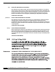
Chapter 1 Product Overview Front Panel Description SFP Module Patch Cable The Cisco ME switch supports the SFP module patch cable, a 1/2 meter, copper, passive cable with SFP module connectors at each end (see Figure 1-3). The patch cable can connect two Cisco ME switches in a cascaded configuration. SFP Module Patch Cable 126809 Figure 1-3 See “Inserting and Removing the SFP Module Patch Cable” section on page 2-21 for more information about using the SFP module patch cable.
Chapter 1 Product Overview Rear Panel Description The System LED shows whether the system is receiving power and is functioning properly. Table 1-1 lists the LED colors and their meanings. Table 1-1 System LED Color System Status Off System is not powered on. Blinking green POST is in progress. Green System is operating normally. Amber System is receiving power but is not functioning properly. Port LEDs Each RJ-45 port and SFP module slot has a port LED.
Chapter 1 Product Overview Management Options Power Connectors These sections describe the power supply features for the Cisco ME AC and DC switches. Cisco ME AC Switch Power Supply The Cisco ME AC switch is powered through an internal power supply. The AC power supply is an autoranging unit that supports input voltages between 100 and 240 VAC. Use the supplied AC power cord to connect the AC power connector to an AC power outlet.
Chapter 1 Product Overview Management Options • SNMP network management You can manage switches from a SNMP-compatible management station that is running platforms such as HP OpenView or SunNet Manager. The switch supports a comprehensive set of Management Information Base (MIB) extensions and four Remote Monitoring (RMON) groups. See the switch software configuration guide on Cisco.com and the documentation that came with your SNMP application for more information.
C H A P T E R 2 Switch Installation This chapter describes how to start your Cisco Metro Ethernet (ME) switch and how to interpret the power-on self-test (POST) that ensures proper operation. It also describes how to install the switch and how to make connections to the switch.
Chapter 2 Switch Installation Preparing for Installation Warning Do not stack the chassis on any other equipment. If the chassis falls, it can cause severe bodily injury and equipment damage. Statement 48 Warning Ethernet cables must be shielded when used in a central office environment. Statement 171 Warning To comply with safety regulations, mount switches on a wall with the front panel facing up.
Chapter 2 Switch Installation Preparing for Installation Warning This unit is intended for installation in restricted access areas. A restricted access area can be accessed only through the use of a special tool, lock and key, or other means of security. Statement 1017 Warning The plug-socket combination must be accessible at all times, because it serves as the main disconnecting device. Statement 1019 Warning A readily accessible two-poled disconnect device must be incorporated in the fixed wiring.
Chapter 2 Switch Installation Preparing for Installation Warning Installation of the equipment must comply with local and national electrical codes. Statement 1074 Caution To comply with the Telcordia GR-1089 Network Equipment Building Systems (NEBS) standard for electromagnetic compatibility and safety, connect the ethernet cables only to intrabuilding or nonexposed wiring or cabling. Note The grounding architecture of this product is DC-isolated (DC-I).
Chapter 2 Switch Installation Preparing for Installation Table 2-1 Fiber-Optic SFP Module Port Cabling Specifications (continued) Modal Bandwidth (MHz/km) Cable Distance 62.5 62.5 50 50 160 200 400 500 722 feet (220 m) 902 feet (275 m) 1640 feet (500 m) 1804 feet (550 m) SMF 62.
Chapter 2 Switch Installation Preparing for Installation • Airflow around the switch and through the vents is unrestricted. • Temperature around the unit does not exceed 113°F (50°C). Note If the switch is installed in a closed or multirack assembly, the temperature around it might be greater than normal room temperature. Verifying Package Contents Note Carefully remove the contents from the shipping container, and check each item for damage.
Chapter 2 Switch Installation Verifying Switch Operation Verifying Switch Operation Before installing the switch in a rack, on a wall, or on a table or shelf, you should power the switch and verify that the switch passes POST. To power on the switch, connect one end of the AC power cord to the AC power connector on the switch, and connect the other end of the power cord to an AC power outlet. To power on a DC switch, see Appendix C, “Connecting to DC Power.
Chapter 2 Switch Installation Installing the Switch . Warning Note To prevent bodily injury when mounting or servicing this unit in a rack, you must take special precautions to ensure that the system remains stable. The following guidelines are provided to ensure your safety: • This unit should be mounted at the bottom of the rack if it is the only unit in the rack.
Chapter 2 Switch Installation Installing the Switch Attaching Brackets to the Switch The bracket orientation and the brackets that you use depend on whether you are attaching the brackets for a 19-inch, 23-inch, 24-inch, or an ETSI rack. Figure 2-2 shows the four types of mounting brackets. Figure 2-2 Rack-Mounting Brackets 19 inch ETSI 23 inch 132869 24 inch • For 19-inch racks, use part number RCKMNT-19IN-1RU (700-08209-XX), and see Attaching Brackets to 19-Inch Racks, page 2-10.
Chapter 2 Switch Installation Installing the Switch Attaching Brackets to 19-Inch Racks These figures show how to attach brackets to 19-inch racks: • Attaching Brackets for 19-Inch Racks to a Cisco ME Switch, Front Panel Forward, Figure 2-3 on page 2-10 • Attaching Brackets for 19-Inch Racks to a Cisco ME Switch, Rear Panel Forward, Figure 2-4 on page 2-10 • Attaching Brackets for 19-Inch Telco Racks to a Cisco ME Switch, Figure 2-5 on page 2-11 Figure 2-3 Attaching Brackets for 19-Inch Racks to a
Chapter 2 Switch Installation Installing the Switch Attaching Brackets for 19-Inch Telco Racks to a Cisco ME Switch Cisco M 132687 Figure 2-5 E 2400 SER IES 1 2 1 1 Phillips flat-head screws Attaching Brackets for 23-Inch Racks These figures show how to attach brackets to 23-inch racks: • Attaching Brackets for 23-Inch Racks to a Cisco ME Switch, Front Panel Forward, Figure 2-6 on page 2-11 • Attaching Brackets for 23-Inch Racks to a Cisco ME Switch, Rear Panel Forward, Figure 2-7 on page 2-
Chapter 2 Switch Installation Installing the Switch Attaching Brackets for 23-Inch Racks to a Cisco ME Switch, Rear Panel Forward 143308 Figure 2-7 1 Phillips flat-head screws Figure 2-8 Attaching Brackets for 23-Inch Telco Racks to a Cisco ME Switch Cisco M 143310 1 E 2400 SER IES 1 2 1 1 Phillips flat-head screws Attaching Brackets to 24-Inch Racks These figures show attaching brackets to 24-inch racks: • Attaching Brackets for 24-Inch Racks to a Cisco ME Switch, Front Panel Forward,
Chapter 2 Switch Installation Installing the Switch Figure 2-9 Attaching Brackets for 24-Inch Racks to a Cisco ME Switch, Front Panel Forward 1 RATIN G 1001A-0.
Chapter 2 Switch Installation Installing the Switch Attaching Brackets for ETSI Racks These figures show attaching brackets to ETSI racks: • Attaching Brackets for ETSI Racks to a Cisco ME Switch, Front Panel Forward, Figure 2-12 on page 2-14 • Attaching Brackets for ETSI Racks to a Cisco ME Switch, Rear Panel Forward, Figure 2-13 on page 2-14 • Attaching Brackets for ETSI Telco Racks to a Cisco ME Switch, Figure 2-14 on page 2-15 Figure 2-12 Attaching Brackets for ETSI Racks to a Cisco ME Switch,
Chapter 2 Switch Installation Installing the Switch Attaching Brackets for ETSI Telco Racks to a Cisco ME Switch Cisco M 132867 Figure 2-14 E 2400 SER IES 1 2 1 1 Phillips flat-head screws Mounting the Switch in a Rack After the brackets are attached to the switch, use the four supplied number-12 Phillips machine screws to securely attach the brackets to the rack, as shown in Figure 2-15. Figure 2-15 Mounting the Cisco ME Switch in a Rack 1 SYSTEM 1X RATING 100 1A-0.
Chapter 2 Switch Installation Installing the Switch Attaching the Cable Guide We recommend attaching the cable guide to prevent the cables from obscuring the front panel of the switch and the other devices installed in the rack. Use the supplied black screw shown in Figure 2-16 to attach the cable guide to the left or right bracket. Figure 2-16 Attaching the Cable Guide on the Cisco ME Switch 1 SYSTEM 1X RATING 100 1A-0.
Chapter 2 Switch Installation Installing the Switch Mounting the Switch on a Wall For the best support of the switch and cables, make sure the switch is attached securely to wall studs or to a firmly attached plywood mounting backboard. Mount the switch with the front panel facing up, as shown in Figure 2-18. To comply with safety regulations, mount switches on a wall with the front panel facing up.
Chapter 2 Switch Installation Installing and Removing SFP Modules Table- or Shelf- Mounting Follow these steps to install the switch on a table or shelf: Step 1 Place the switch on the table or shelf near an AC power source. Step 2 After the switch is placed on the table or shelf, you need to do these tasks to complete the installation: • Power on the switch. See the “Verifying Switch Operation” section on page 2-7. • Connect to a 10/100 port, and run the Initial Configuration Dialog.
Chapter 2 Switch Installation Installing and Removing SFP Modules SFP Module with a Bale-Clasp Latch 86575 Figure 2-19 To insert an SFP module into the module slot, follow these steps (see Figure 2-20): Step 1 Attach an ESD-preventive wrist strap to your wrist and to a bare metal surface on the chassis. Step 2 Find the send (TX) and receive (RX) markings that identify the top side of the SFP module.
Chapter 2 Switch Installation Installing and Removing SFP Modules Step 6 Insert the cable connector into the SFP module: • For fiber-optic SFP modules, insert the LC or MT-RJ cable connector into the SFP module. • For copper 1000BASE-T SFP modules, insert the RJ-45 cable connector into the SFP module. Note When connecting to 1000BASE-T SFP modules, be sure to use a twisted four-pair, Category 5 cable.
Chapter 2 Switch Installation Inserting and Removing the SFP Module Patch Cable Inserting and Removing the SFP Module Patch Cable To insert an SFP module patch cable into the SFP module slot, follow these steps: Step 1 Attach an ESD-preventive wrist strap to your wrist and to a bare metal surface on the chassis. Step 2 Insert the SFP module patch cable into the slot until you feel the connector on the cable snap into place in the rear of the slot (see Figure 2-22).
Chapter 2 Switch Installation Connecting to the 10/100 Ports Connecting to the 10/100 Ports The switch 10/100 ports configure themselves to operate at the speed of attached devices. If the attached ports do not support autonegotiation, you can explicitly set the speed and duplex parameters. Connecting devices that do not autonegotiate or that have their speed and duplex parameters manually set can reduce performance or result in no linkage.
Chapter 2 Switch Installation Connecting to SFP Modules Step 3 Reconfigure and reboot the connected device, if necessary. Step 4 Repeat Steps 1 through 3 to connect each device. Connecting to SFP Modules This section describes how to connect to SFP modules. For instructions on how to connect to fiber-optic SFP modules, see the “Connecting to Fiber-Optic SFP Modules” section. For instructions on how to connect to copper 1000BASE-T SFP modules, see the “Connecting to 1000BASE-T SFP Modules” section.
Chapter 2 Switch Installation Connecting to SFP Modules Step 4 Observe the port status LED. The LED turns green when the switch and the target device have an established link. The LED turns amber while the STP discovers the network topology and searches for loops. This process takes about 30 seconds, and then the port LED turns green. If the LED is off, the target device might not be turned on, there might be a cable problem, or there might be problem with the adapter installed in the target device.
Chapter 2 Switch Installation Where to Go Next Step 3 Observe the port status LED. The LED turns green when the switch and the target device have an established link. The LED turns amber while the STP discovers the network topology and searches for loops. This process takes about 30 seconds, and then the port LED turns green. If the LED is off, the target device might not be turned on, there might be a cable problem, or there might be problem with the adapter installed in the target device.
Chapter 2 Switch Installation Where to Go Next Cisco ME 2400 Ethernet Access Switch Hardware Installation Guide 2-26 OL-7678-01
C H A P T E R 3 Troubleshooting The System and port LEDs on the front panel provide troubleshooting information about the switch. They show failures in the power-on self-test (POST), port-connectivity problems, and overall switch performance. For a full description of the switch LEDs, see the “LEDs” section on page 1-5. You can also get statistics from the browser interface, from the command-line interface (CLI), or from a Simple Network Management Protocol (SNMP) workstation.
Chapter 3 Troubleshooting Diagnosing Problems Table 3-1 describes how to detect and resolve these problems. Table 3-1 Common Problems and Their Solutions Symptom Possible Cause Resolution Poor performance or excessive errors Duplex autonegotiation mismatch. See the switch software configuration guide for information on identifying autonegotiation mismatches. Cabling distance exceeded • Port statistics show excessive frame check sequence (FCS), late-collision, or alignment errors.
Chapter 3 Troubleshooting Diagnosing Problems Table 3-1 Common Problems and Their Solutions (continued) Symptom Possible Cause No connectivity Incorrect or bad cable Resolution These are results of no link at both ends: • A crossover cable was used when a straight-through was required, or the reverse. • For the correct pinouts and the proper application of crossover instead of straight-through cables, see the “Two Twisted-Pair Cable Pinouts” section on page B-3.
Chapter 3 Troubleshooting Diagnosing Problems Table 3-1 Common Problems and Their Solutions (continued) Symptom Possible Cause Resolution Switch does not recognize the SFP module The SFP module might be installed upside down. Verify that the SFP module is not installed upside down. The SFP module does not snap into the slot. Remove the SFP module. Inspect for physical damage to the connector, the module, and the module slot. Replace the SFP module with a known good SFP module.
A P P E N D I X A Technical Specifications This appendix lists the switch technical specifications in Table A-1. Table A-1 Technical Specifications for the Cisco ME 2400 Ethernet Access Switch Environmental Ranges Operating temperature 32 to 113°F (0 to 50°C) Storage temperature –13 to 158°F (– 25 to 70°C) Relative humidity 10 to 85% (noncondensing) Operating altitude Up to 10,000 ft (3049 m) Storage altitude Up to 15,000 ft (4573 m) AC Power Requirements AC input voltage 100 to 240 VAC 0.
Appendix A Technical Specifications Cisco ME 2400 Ethernet Access Switch Hardware Installation Guide A-2 OL-7678-01
A P P E N D I X B Connector and Cable Specifications This appendix describes the Cisco ME switch ports and the cables and adapters that you use to connect the switch to other devices. Connector Specifications These sections describe the connectors used with the switch. 10/100 Ports The 10/100 Ethernet ports use standard RJ-45 connectors and Ethernet pinouts with internal crossovers.
Appendix B Connector and Cable Specifications Connector Specifications Note You can use the mdix auto interface configuration command in the CLI to enable the automatic medium-dependent interface crossover (auto-MDIX) feature. When the auto-MDIX feature is enabled, the switch detects the required cable type for copper Ethernet connections and configures the interfaces accordingly.
Appendix B Connector and Cable Specifications Cable and Adapter Specifications Copper SFP Module RJ-45 Connector Pin Label 1 TP0+ 2 TP0- 3 TP1+ 4 TP2+ 5 TP2- 6 TP1- 7 TP3+ 8 TP3- 1 2 3 4 5 6 7 8 60915 Figure B-3 Console Port The console port uses an 8-pin RJ-45 connector, which is described in Table B-1 and Table B-2. If you did not order a console cable with your switch, you need to provide an RJ-45-to-DB-9 adapter cable to connect the console port of the switch to a console PC.
Appendix B Connector and Cable Specifications Cable and Adapter Specifications Two Twisted-Pair Crossover Cable Schematic Switch Switch 3 TD+ 6 TD– 3 TD+ 6 TD– 1 RD+ 2 RD– 1 RD+ 2 RD– H5579 Figure B-5 Four Twisted-Pair Cable Pinouts for 1000BASE-T Ports Figure B-6 and Figure B-7 show the schematics of four twisted-pair cables for 1000BASE-T SFP module ports on Cisco ME switches.
Appendix B Connector and Cable Specifications Cable and Adapter Specifications Crossover Cable and Adapter Pinouts This section describes how to identify a crossover cable and also describes the adapter pinouts. Identifying a Crossover Cable To identify a crossover cable, compare the two modular ends of the cable. Hold the cable ends side-by-side, with the tab at the back.
Appendix B Connector and Cable Specifications Cable and Adapter Specifications Table B-2 lists the pinouts for the console port, RJ-45-to-DB-25 female DTE adapter, and the console device. Note The RJ-45-to-DB-25 female DTE adapter is not supplied with the switch. You can order a kit (part number ACS-DSBUASYN=) containing this adapter from Cisco.
A P P E N D I X C Connecting to DC Power To connect the Cisco ME switch to a DC-input power source, follow these steps: 1. Preparing for Installation, page C-1 2. Grounding the Switch, page C-2 3. Wiring the DC-Input Power Source, page C-5 Warning Ethernet cables must be shielded when used in a central office environment. Statement 171 Warning This unit is intended for installation in restricted access areas.
Appendix C Connecting to DC Power Grounding the Switch • 6-gauge copper ground wire (insulated or noninsulated) • Four leads of 18-gauge copper wire • Wire-stripping tools for stripping 6- and 18-gauge wires Grounding the Switch Warning This equipment is intended to be grounded. Ensure that the host is connected to earth ground during normal use. Statement 39 Warning When installing the unit, always make the ground connection first and disconnect it last.
Appendix C Connecting to DC Power Grounding the Switch Crimping the Ground Lug 60529 Figure C-2 Use the two number-10-32 screws to attach the ground lug and wire assembly to the rear panel of the switch. Step 6 Using a ratcheting torque screwdriver, torque each ground-lug screw to 15 lbf-in. (240 ounce-force inches [ozf-in.]). Figure C-3 shows how to torque the ground screws on a Cisco ME DC switch. Torquing Ground-Lug Screws 132854 Figure C-3 Step 5 1 1 Torque to 15 lbf-in.
Appendix C Connecting to DC Power Grounding the Switch Connecting the Grounding Wire to Earth Ground Next you must connect the other end of the grounding wire to an appropriate grounding point at your site or to the telco rack. You can connect the grounding wire to either the front panel ground connector (see Figure C-4) or the rear panel ground connector (see Figure C-5), but not to both.
Appendix C Connecting to DC Power Wiring the DC-Input Power Source Complete these steps: Step 1 Remove all paint or oxidation from the rack at the point of the grounding connection. Step 2 Use a 3/16-inch flat-head screwdriver to loosen the grounding screw on the rack. Step 3 Connect the wire to a ring lug (large enough for the rack screw to fit through). Step 4 Use a 3/16-inch flat-head screwdriver and the screw to attach the ring lug to the rack.
Appendix C Connecting to DC Power Wiring the DC-Input Power Source Terminal Block Plug 60530 Figure C-6 Step 3 Identify the positive and negative feed positions for the terminal block connection. The wiring sequence is positive to positive and negative to negative for both the A and the B feed wires. The front panel of the switch identifies the positive and negative positions for both the A and B feed wires (See Figure C-7.
Appendix C Connecting to DC Power Wiring the DC-Input Power Source Warning An exposed wire lead from a DC-input power source can conduct harmful levels of electricity. Be sure that no exposed portion of the DC-input power source wire extends from the terminal block plug.
Appendix C Connecting to DC Power Wiring the DC-Input Power Source Figure C-10 Torquing the Terminal-Block Captive Screws 60533 Torque to 4.5 lbf-in. (72 ozf-in.) Step 7 Repeat Steps 4 and 5 for the remaining three DC-input power source wires. Figure C-11 shows the completed wiring of a terminal block plug.
Appendix C Connecting to DC Power Wiring the DC-Input Power Source Caution Secure the wires coming in from the terminal block so that they cannot be disturbed by casual contact. For example, use tie wraps to secure the wires to the rack. Figure C-12 Inserting the Terminal Block in the Block Header SYSTEM + CONSO LE Step 9 132851 + A INPUT -3 B CURRE 6 – -72 V NT 2 – 1A Remove the tape from the circuit-breaker switch handle, and move the circuit-breaker handle to the on position.
Appendix C Connecting to DC Power Wiring the DC-Input Power Source Cisco ME 2400 Ethernet Access Switch Hardware Installation Guide C-10 OL-7678-01
A P P E N D I X D Configuring the Switch with the CLI-Based Setup Program This appendix provides a command-line interface (CLI)-based setup procedure for a standalone switch. For product overview information, see Chapter 1, “Product Overview.” Before connecting the switch to a power source, review the safety warnings in Chapter 2, “Switch Installation.
Appendix D Configuring the Switch with the CLI-Based Setup Program Accessing the CLI Through the Console Port Taking Out What You Need Remove the items shown in Figure D-1 from the shipping container: Figure D-1 1 The Cisco ME Switch, Adapter Cable, and AC Power Cord SYSTEM 1 2 1X + 3 4 5 6 7 8 + A INPUT -36 B CURRENT – -72 V 2 – 1A 9 10 11 12 13 11X 14 13X CONSOL 15 16 17 18 E 19 20 21 22 2X 23 24 23X Cisco ME 12X 14X 2400 SERIES 1 24X 2 132697 2 3 1 2 Cisc
Appendix D Configuring the Switch with the CLI-Based Setup Program Connecting to the Console Port Note You need to provide the Category 5 straight-through cables to connect the switch ports to other Ethernet devices. Note You can use the CLI mdix auto interface configuration command to enable the automatic medium-dependent interface crossover (auto-MDIX) feature.
Appendix D Configuring the Switch with the CLI-Based Setup Program Starting the Terminal-Emulation Software Figure D-3 Connecting the Switch to a PC 1 1 SYSTEM 1X RATING 100-240 V~ 1A-0.
Appendix D Configuring the Switch with the CLI-Based Setup Program Connecting to a Power Source Connecting to a Power Source Follow these steps to connect to an AC power source: Step 1 Connect one end of the supplied AC power cord to the power connector on a switch rear panel. See Figure D-2. Step 2 Connect the other end of the power cable to a grounded AC outlet. Follow these steps to connect to an DC power source.
Appendix D Configuring the Switch with the CLI-Based Setup Program Entering the Initial Configuration Information Completing the Setup Program Follow these steps to complete the setup program and to create an initial configuration for the switch: Step 1 Enter Yes at these two prompts. Would you like to enter the initial configuration dialog? [yes/no]: yes At any point you may enter a question mark '?' for help. Use ctrl-c to abort configuration dialog at any prompt.
Appendix D Configuring the Switch with the CLI-Based Setup Program Entering the Initial Configuration Information Step 9 Enter Y to configure the switch as the cluster command switch. Enter N to configure it as a member switch or as a standalone switch. If you enter N, you can configure the switch as a command switch later through the CLI. To configure it later, enter no.
Appendix D Configuring the Switch with the CLI-Based Setup Program Entering the Initial Configuration Information Cisco ME 2400 Ethernet Access Switch Hardware Installation Guide D-8 OL-7678-01
I N D EX Numerics B 10/100 ports brackets cable lengths 2-4 See mounting brackets connecting to 2-22 connectors and cables described 1-3 illustrated 1-2 B-1 to B-2 C cable guide, attaching 1000BASE-BX SFP module 1-4 1000BASE-LX/LH SFP module 1000BASE-SX SFP module 1000BASE-T SFP module cable lengths 1-4 2-4 cables 1-4 crossover 1-4 four twisted-pair pinout, 1000BASE-T ports 1000BASE-T SFP module cable lengths 1000BASE-ZX SFP module 2-16 2-4 identifying 1-4 B-5 two twisted-pai
Index coarse wavelength-division multiplexing disposal of product warning document conventions See CWDM 2-3 viii command-line interface See CLI configuration examples, network E 1-1 connecting electrical code compliance warning to 10/100 ports 2-22 electrical noise, avoiding to console port B-3 Ethernet cable warning to DC power 2-7 to SFP modules to the console port ETSI racks D-3 connection procedures 2-2, C-1 2-22 to 2-25 B-1 console port B-3 to B-6 SFP module ports 2-7 See
Index I N installation network configuration examples assigning the IP Address connecting to a power source rack-mounting 2-7 to 2-15 shelf-mounting 2-18 site requirements noise, electrical D-5 O overcurrent protection warning starting the terminal emulation software 2-18 wall-mounting 2-16 D-4 overheating warning 2-2, C-5 2-3 P See also procedures installation warning 2-5 2-7, D-5 2-4 table-mounting 1-1 2-1, C-5 installing SFP modules 2-18 to 2-20 packing list 2-6 performan
Index power 100BASE-BX 1-4 connecting to AC 2-7 100BASE-FX 1-4 connecting to DC 2-7 100BASE-LX 1-4 power on bale-clasp latch removal 2-7 power-on self-test connecting to connectors see POST power source warning CWDM 2-2 power supply 1-4 1-4 installation 1-7 procedures 2-23 to 2-25 B-2 described AC power outlet 2-20 2-18 to 2-20 shelf-mounting 2-18 connection 2-22 to 2-25 short-circuit protection warning installation 2-7 to 2-18 Simple Network Management Protocol produc
Index U user-serviceable parts warning 2-3 W wall-mounting 2-16 wall-mounting warning 2-2 warnings Class 1 laser DC power defined 2-2 2-2, C-5 viii disposal of product 2-3 electrical code compliance Ethernet cable C-1 exposed DC power wire ground conductor C-7 2-3 ground connection 2-3, C-2 grounded equipment installation C-2 2-1, C-5 jewelry removal 2-1 lightning activity 2-2 no user-serviceable parts overheating 2-4 2-3 2-3 plug-socket combination power source 2-3 2-2 rack
Index Cisco ME 2400 Ethernet Access Switch Hardware Installation Guide IN-6 OL-7678-01