Cisco ME 6500 Series Ethernet Switch Installation Note This publication contains the procedures for installing, cabling, and powering up the Cisco ME 6500 series Ethernet switch. For complete information about installing the Cisco ME 6500 series Ethernet switch, see the Cisco ME 6500 Series Ethernet Switch Installation Guide on Cisco.com. For configuration information, see the Cisco ME 6500 Series Ethernet Switch Software Configuration Guide.
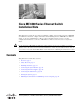
Overview Overview The Cisco ME 6524 Ethernet switch is an Ethernet access switch in a 1.5 RU standalone chassis. There are two models of the Cisco ME 6524 Ethernet switch: • ME-C6524GS-8S—This model of the Cisco ME 6524 Ethernet switch has 24 Ethernet SFP downlink ports and 8 Ethernet SFP uplink ports. SFP transceivers must be installed in the port sockets for the ports to be active.
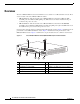
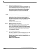
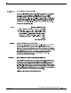
Overview Figure 2 Cisco ME 6524 Ethernet Switch (ME-C6524GT-8S) Front Panel Features 7 9 1 3 5 7 4 9 6 11 8 CONS OLE 13 10 15 12 14 PS2 17 15 19 18 FAN 21 20 23 22 24 STATU S 1 2 3 4 5 6 Catalyst 6524GS USB 7 8 9 25 27 10 11 12 13 14 16 17 18 31 28 30 32 19 20 21 22 23 24 1 25 26 3 2 29 26 FLASH 15 180415 2 PS1 8 4 27 28 29 30 31 32 6 5 1 Status LEDs and RESET switch 6 Uplink port status LEDs 2 CONSOLE port (RJ-45 connector)
Safety Overview Safety Overview Safety warnings appear throughout this publication in procedures that may harm you if performed incorrectly. A warning symbol precedes each warning statement. Statement 1071—Warning Definition Warning IMPORTANT SAFETY INSTRUCTIONS This warning symbol means danger. You are in a situation that could cause bodily injury.
Safety Overview Attention IMPORTANTES INFORMATIONS DE SÉCURITÉ Ce symbole d'avertissement indique un danger. Vous vous trouvez dans une situation pouvant entraîner des blessures ou des dommages corporels. Avant de travailler sur un équipement, soyez conscient des dangers liés aux circuits électriques et familiarisez-vous avec les procédures couramment utilisées pour éviter les accidents.
Safety Overview Aviso INSTRUÇÕES IMPORTANTES DE SEGURANÇA Este símbolo de aviso significa perigo. Você está em uma situação que poderá ser causadora de lesões corporais. Antes de iniciar a utilização de qualquer equipamento, tenha conhecimento dos perigos envolvidos no manuseio de circuitos elétricos e familiarize-se com as práticas habituais de prevenção de acidentes.
Safety Overview Cisco ME 6500 Series Ethernet Switch Installation Note 78-17360-02 7
Safety Overview Aviso INSTRUÇÕES IMPORTANTES DE SEGURANÇA Este símbolo de aviso significa perigo. Você se encontra em uma situação em que há risco de lesões corporais. Antes de trabalhar com qualquer equipamento, esteja ciente dos riscos que envolvem os circuitos elétricos e familiarize-se com as práticas padrão de prevenção de acidentes. Use o número da declaração fornecido ao final de cada aviso para localizar sua tradução nos avisos de segurança traduzidos que acompanham o dispositivo.
Safety Overview Cisco ME 6500 Series Ethernet Switch Installation Note 78-17360-02 9
Safety Overview Installation Warning Statements This section includes the basic installation warning statements. Translations of these warning statements appear in the Regulatory Compliance and Safety Information for the Cisco ME 6500 Series Ethernet Switch document that shipped with the chassis. Warning Only trained and qualified personnel should be allowed to install, replace, or service this equipment.
Safety Overview Warning To prevent bodily injury when mounting or servicing this unit in a rack, you must take special precautions to ensure that the system remains stable. The following guidelines are provided to ensure your safety: • This unit should be mounted at the bottom of the rack if it is the only unit in the rack. • When mounting this unit in a partially filled rack, load the rack from the bottom to the top with the heaviest component at the bottom of the rack.
Installing the Switch Installing the Switch The Cisco ME 6524 Ethernet switch is installed in a standard 19-inch rack. This section provides procedures that you can use to install the switch chassis in the rack. For additional installation information, see the Cisco ME 6500 Series Ethernet Switch Installation Guide on Cisco.com. Note The chassis is designed to be mounted in equipment racks that meet ANSI/EIA 310-D and ETS 300-119 standards.
Installing the Switch Attaching the L Brackets Use eight M4 Phillips countersunk-head screws to attach the long side of the L brackets to the Cisco ME 6524 Ethernet switch chassis. The L brackets can be attached to the chassis in two mounting positions: either at the front of the chassis or at the rear of the chassis. (See Figure 4.
Installing the Switch Rack-Mounting the Switch Use six 10-32 x 3/4-inch or 12-24 x 3/4-inch Phillips machine screws to attach the L brackets to the rack. (See Figure 5.
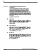
Connecting the System Ground Figure 6 Installing the Rubber Feet OUTPUT INPUT OK FAN OK OK + - 147981 OUTPUT INPUT OK FAN OK OK + - o o Connecting the System Ground The system (NEBS) ground provides additional grounding for EMI shielding requirements and is intended to satisfy the Telcordia Technologies NEBS requirements for supplemental bonding and grounding connections. Note The ground lug and the ground lug screws are supplied as part of the accessory kit.
Connecting the Power Supplies Step 3 Place the ground lug against the ground pad, making sure that there is solid metal-to-metal contact, and secure it to the chassis with two M4 screws. Ensure that the ground lug and the ground wire do not interfere with other cables or equipment. Step 4 Prepare the other end of the system ground wire and connect it to an appropriate ground point in your site to ensure adequate earth ground for the switch.
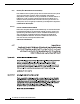
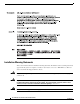
Connecting the Power Supplies Warning When installing or replacing the unit, the ground connection must always be made first and disconnected last. Statement 1046 To attach source DC power cables to the DC-input power supply (see Figure 8), follow these steps: Step 1 Verify that the system (NEBS) ground connection has been installed. Step 2 Verify that power is off to the DC circuit that feeds the power supply that you are installing.
Connecting the Power Supplies Figure 8 Cabling the DC-Input Power Supply Cisco ME 6500 Series Ethernet Switch Installation Note 18 78-17360-02
Connecting the Power Supplies Connecting an AC-Input Power Supply If your chassis is equipped with AC-input power supplies, you need to run the AC power cord from the source AC to the AC-in connector on the AC-input power supply. To attach the AC power cord between source AC and the AC-input power supply (see Figure 9), follow these steps: Step 1 Verify that the system (NEBS) ground connection has been installed. Step 2 Remove the AC power cord from its packaging.
Connecting the Switch Ports Connecting the Switch Ports The Cisco ME 6524 Ethernet switch has 1 console port, 24 downlink ports, and 8 uplink ports. This section describes how to connect to the console port, downlink ports, and uplink ports. Connecting the Console Port A console port cable equipped with RJ-45 connectors is included in the accessory kit. Plug one end of the cable into the RJ-45 CONSOLE port connector on the switch chassis front panel.
Connecting the Switch Ports To install the SFP transceiver and to connect the optical network cables, follow these steps: Step 1 Attach an ESD-preventive wrist strap to your wrist and to the ESD ground connector on your chassis. Step 2 Remove the SFP transceiver from its protective packaging. Step 3 Check the label on the SFP transceiver body to verify that you have the correct model for your network and locate the send (Tx) and receive (Rx) markings that identify the top side of the SFP transceiver.
Connecting the Switch Ports Cleaning the SFP Transceiver Optics For optical SFP transceivers, before making any optical connections, observe the following guidelines: • Always keep the protective dust plugs on the unplugged fiber-optic cable connectors and the transceiver optical bores until you are ready to make a connection. • Always inspect and clean the LC connector end-faces just before making any connections. • Always grasp the LC connector housing to plug or unplug a fiber-optic cable.
Starting the System Starting the System To power up the system, follow these steps: Step 1 Before you start the system, verify the following: • All interface cables are secure. • Each power supply is connected to a grounded power source. • If both power supplies are installed, each power supply is connected to a different source circuit. • System ground is attached to the system. • A terminal is connected to the console port. Step 2 Set the power switch on each power supply to on (|).
Obtaining Documentation and Submitting a Service Request Obtaining Documentation and Submitting a Service Request For information on obtaining documentation, submitting a service request, and gathering additional information, see the monthly What’s New in Cisco Product Documentation, which also lists all new and revised Cisco technical documentation, at: http://www.cisco.com/en/US/docs/general/whatsnew/whatsnew.