CHAPTER 6 Card and Service Configuration This chapter describes how to configure the MGX 8850 cards and the services they support. Although the presumption for this chapter is that a plan exists for your network, it reviews some of the information that supports network planning. Generic instructions for inserting and removing cards appear in “Chapter 4, “Enclosure and Card Installation.
Tasks for Configuring Cards and Services PXM, the connections are global logical connections (GLCNs). By default, all resources on a a card or logical port are available to any controller on a first-come, first-served basis. If necessary, you can modify the resource partitioning at the card level or logical port level. Port-level resource modification follows card-level modification, so the available port-level resources depend on whether and how much you change the card-level resource partitioing.
Rules for Adding Connections Rules for Adding a DAX Connection A DAX con is a connection whose endpoints for the entire connection exist on the same switch. The following apply to the MGX 8850 switch: 1 On a feeder, a DAX con can exist between different service modules or the same service module. 2 A stand-alone node supports DAX cons with one or both endpoints on the PXM in addition to DAX cons between service modules. 3 Either endpoint can be the master. 4 The first endpoint to add is the slave.
Tasks for Configuring Cards and Services Rules for Adding Management Connections This section describes the requirements for adding an inband ATM PVC for managing an MGX 8850 stand-alone node. A management connection lets a workstation connected through a router control either the local MGX 8850 node or a remote MGX 8850 node that has no workstation. The typical configuration has the connecting router feed an AUSM/B, FRSM, RPM, or PXM UNI port.
The Processor Switching Module The Processor Switching Module This section first describes how to activate and configure the card-level parameters, lines, and ports on the PXM uplink card then describes how to add connections to the PXM in a stand-alone node. The descriptions tell you how to: • • Optionally modify the resource partitioning at the card level.
The Processor Switching Module Configuring Card-Level Parameters, Lines, and Ports This section describes how to configure card-level features, activate a physical line, and configure logical elements such as a port. If necessary, refer to the section titled “Tasks for Configuring Cards and Services” for background information on these types of tasks. Step 1 Optionally, you can modify the resource partitioning for the whole card by executing cnfcdrscprtn.
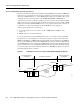
Automatic Protection Switching on the PXM Using an example of 100% of the bandwidth on one logical port 1: addport 1 1 100 1 200 where the first “1” is the logical port number; the second “1” is the line number on the PXM back card to which you are assigning this logical port number; “100” is the percentage of bandwidth this port has in both directions; and the VPI range is 1–200.
The Processor Switching Module Initial APS specification consists of the working and protection slot and line and the mode for APS. After the initial APS specification, you can configure additional APS parameters, give commands for switching lines, and display the APS configuration. The CiscoView application and CLI provide access to the APS feature. For detailed descriptions of the CLI commands, see the Cisco MGX 8850 Wide Area Edge Switch Command Reference.
Adding Connections on a PXM in a Stand-Alone Node Adding Connections on a PXM in a Stand-Alone Node This section describes the CLI commands for provisioning connections on a PXM in a stand-alone node. Connection addition abides by the rules for a standard connection or a management connection in the form of either a three-segment connection or a DAX con. See “Rules for Adding Connections” earlier in this chapter.
The Processor Switching Module Step 3 As needed, specify usage parameter control according to the connection type. Use either cnfupccbr, cnfupcvbr, cnfupcabr, or cnfupcubr. The following text lists the parameters for each. Note that the parameters for cnfupcvbr and cnfupcabr are the same. Also, the polType (policing type) parameter has numerous variations in accordance with ATM Forum v4.0. For a list of the policing variations, see Table 6-1 after the syntax descriptions.
Adding Connections on a PXM in a Stand-Alone Node Table 6-1 Policing Definitions According to Policing and Connection Type Policing by Connection Type ATM Forum TM spec. 4.0 conformance definition PCR Flow (1st leaky bucket) CLP tagging (for PCR flow) SCR Flow (2nd leaky bucket) CLP tagging (for SCR flow) CBR CBR.1 CLP(0+1) no off n/a polType=4 (PCR Policing only) CBR When policing = 5 (off) off n/a off n/a UBR UBR.
ATM Universal Service Module ATM Universal Service Module The eight-port ATM Universal Service Module (MGX-AUSM/B-8T1 and MGX-AUSM/B-E1) is a multipurpose card set with eight T1 or E1 lines that support: • ATM UNI with high port-density for the CPE—with AUSMs in all 24 service module slots, an MGX 8850 switch can support up to 192 individual T1 or E1 lines. An individual card set can support 1000 data connections and 16 management connections.
Using the CLI to Configure the Card, Lines, and Ports On the CLI of the AUSM/B: Step 1 If necessary, modify the resource partitioning for the whole card by executing the cnfcdrscprtn command. You can view resource partitioning through dspcdrscprtn. cnfcdrscprtn • • • number_PAR_conns is the number of connections in the range 0–1000 for PAR. number_PNNI_conns is the number of connections in the range 0–1000 for PNNI.
ATM Universal Service Module cnfportrscprtn [VCImin/VCImax] • • • • • • • port_num is the port number in the range 1–8. controller is a number representing the controller: 1=PAR, 2=PNNI, and 3=MPLS. ingress_%BW is the percentage of ingress bandwidth in the range 0–100. egress_%BW is the percentage of egress bandwidth in the range 0–100. number_of_cons is the maximum number of connections on the port.
Adding and Configuring Connections on the AUSM/B On the CLI of the AUSM/B: Step 1 Execute the addcon command. When you add a connection with addcon, the system automatically assigns the next available channel number, so addcon does not require it. However, some related commands require a channel number—cnfchanfst, cnfchanq, and cnfupcabr, for example. To see the channel number after you add a connection, use dspcons.
ATM Universal Service Module EgSrvRate is the egress service rate. Without IMA, the range is as follows: T1, 10–3622 cells per second E1, 10–4528 cells per second clear E1, 10–4830 cells per second For IMA, multiply the line rate by the number of links. EgrPcUtil is the percent utilization on the egress. The range is 1–127. The default is 0. cnfupcvbr has the same syntax and parameters as cnfupcabr cnfupcvbr or cnfupcabr
Adding and Configuring Connections on the AUSM/B cnfupcubr port.vpi.vci identifies the connection. enable is the enabled/disable for UPC: 1=Disable, 2=Enable. pcr is the peak cell rate. Without IMA, the range is: T1, 10–3622 E1, 10–4528 clear E1, 10–4830 For IMA, multiply the line rate by the number of links. cdvt cdvt[0+1] is the cell delay variation tolerance for cells with CLP=[0+1]. The range is 1–250000 micro seconds.
ATM Universal Service Module mcr is the minimum cell rate. Without IMA, the range is: T1, 0–3622 E1, 0–4528 clear E1, 0–4830 For IMA, multiply the line rate by the number of links. icr is the initial cell rate. Without IMA, the range is as follows: T1, 0–3622 E1, 0–4528 clear E1, 0–4830 For IMA, multiply the line rate by the number of links. Step 4 If necessary, change the queue depths by using cnfchanq. cnfchanq
Frame Service Module Features Frame Service Module Features This section describes the features available on each of the Frame Service Modules (FRSMs). For descriptions of how to set up these cards and add connections, see the subsequent section titled “Configuring Frame Relay Service.
Frame Service Module Features Four-Port Unchannelized Frame Service Module for V.35 The MGX-FRSM-HS1/B provides unchannelized Frame Relay service across four V.35 lines. The maximum throughput for the card is 16 Mbps. The maximum rate on a line is 8 Mbps. Without the cost of a T3 or E3 card, the MGX-FRSM-HS1/B provides greater that T1 or E1 speeds on a port as well as a choice of 50 line rates in the range 48 Kbps–8 Mbps.
Frame Service Module Features • Standards-based management tools. Each FRSM supports SNMP, TFTP for configuration and statistics collection, and a command line interface. The Cisco WAN Manager application provides full graphical user interface support for connection management. The CiscoView application provides equipment management. • MGX 8800-series network management functions, including image download, configuration upload, statistics, telnet, UI, SNMP, trap, and MIBs.
Frame Service Module Features MGX-FRSM-HS2/B Features The specific features are: • • • • • • • • Up to 1000 user-connections Maximum 2 logical ports Two HSSI lines with configurable line speeds in multiples of 56 Kbps or 64 Kbps Selectable DTE or DCE mode for each port In DCE mode, per port clock speeds of NxT1 and NxE1 up to 52 Mbps Various DTE/DCE loopback operations Maximum possible number of DLCIs per port by using the Q.922 two-octet header format.
Description of Connection Types on the FRSM Description of Connection Types on the FRSM The following sections describe NIW, SIW, FUNI, and frame forwarding. Topics include translation and congestion management. Frame Relay-to-ATM Network Interworking FR-ATM network interworking (NIW) supports a permanent virtual connection (PVC) between two Frame Relay users over a Cisco network or a multi-vendor network. The traffic crosses the network as ATM cells.
Description of Connection Types on the FRSM PVC Status Management The management of ATM layer and FR PVC status management can operate independently. The PVC status from the ATM layer is used when determining the status of the FR PVC. However, no direct actions of mapping LMI A bit to OAM AIS is performed.
Frame Relay-to-ATM Service Interworking • CLP is always 1. In the ATM-to-Frame Relay direction, you can specify a CLP-to-DE mapping scheme for an individual connection: • If one or more ATM cells belonging to a frame has CLP=1, the DE field of the Frame Relay frame is set. • • DE is always 0. DE is always 1. Congestion Indication This section describes congestion indictors. You can modify the CLP and congestion indicators for individual connections. On the CLI, use the cnfchanmap command.
Description of Connection Types on the FRSM Command and Response Mapping The FRSM provides command and response mapping in both directions: • In the Frame Relay-to-ATM direction, the FRSM maps the C/R bit of the received Frame Relay frame to the CPCS-UU least significant bit of the AAL5 CPCS PDU. • In the ATM-to-Frame Relay direction, the FRSM maps the least significant bit of the CPCS-UU to the C/R bit of the Frame Relay frame.
Configuring Frame Relay Service Configuring Frame Relay Service This section first describes how to configure the FRSM card, lines, and ports, then describes how to add connections. The descriptions are for the CLI execution of the tasks. You can also configure the FRSM card, lines, and ports by using the CiscoView application. Refer to the CiscoView documentation for the directions. Also, the easiest way to add connections is by using the Cisco WAN Manager application.
Configuring Frame Relay Service Table 6-2 Supported Lines rates on the MGX-FRSM-HS1/B 1–50 Correspond to Line Rates in Kbps.
Configuring the FRSM Cards, Lines, and Ports • line_num is the DS1 number in the range 1–56 to which you assign the DS0 when both lines are active. If you activate only one line, the range is 1–28. You can assign up to 24 contiguous DS0s to one DS1. Each physical line supports up to 28 DS1s. The number of DS0s cannot span more than DS1. • ds0_speed is a number representing the DS0 speed: 1 for 56 Kbps or 2 for 64 Kbps. • begin_slot is the beginning DS0 timeslot in 1 base.
Configuring Frame Relay Service Step 6 • lmi_sig specifies the LMI signaling. 1=Other, 2=None, 3=StrataLMI, 4=AnnexAUNI, 5=AnnexDUNI, 6=AnnexANNI, 7=AnnexDNNI LMI signalling, N=none, S=StrataLMI, and au=AnnexAUNI. • • • asyn enables asynchronous updates: (y)es or (n)o • T392 sets the T392 timer. The range is 5–30 seconds. It sets the interval in seconds for UNI status polling. The default is 15. • N391 sets the N391 counter–the number of UNI/NNI polling cycles. The range is 1–255. The default is 6.
Adding a Frame Relay Connection Note The following step applies to Y-cable redundancy for the MGX-FRSM-2T3E3. For 1:N redundancy on the eight-port FRSMs, refer to “Redundancy Support by the MGX-SRM-3T3/B.” Step 7 Optionally configure Y-cable redundancy if you have connected the lines of adjacent MGX-FRSM-2T3 or MGX-FRSM-2E3 cards through a Y-cable. The applicable commands are addred, dspred, and delred.
Configuring Frame Relay Service • mastership indicates if this end of the connection is master or slave: 1=master, 2=slave. • connID is the connection identifier at the remote end. It appears in the syntax as an optional parameter because it is mandatory only when you add the connection at the master end. See “Rules for Adding Connections” at the beginning of this chapter. connID can have one the following formats according to the slave endpoint: Nodename.SlotNo.PortNo.DLCI Nodename.SlotNo.PortNo.
Adding a Frame Relay Connection • CIR specifies the committed information rate. The range is 0–10000000 bps (although the V.35 version supports a maximum of 8 Mbps sustained). • chan_type is a number that identifies the channel type: 1=NIW. 2=transparent SIW. 3=SIW with translation. 4=FUNI. 5=frame forwarding. • • • • CAC enables connection admission control. • connID is the “remote” connection identifier from the slave end if you need to enter it at the master end.
Configuring Frame Relay Service CLP to DE is a number in the range 1–4 that specifies the CLP to DE mapping. 1=map CLP to DE 2=set DE to 0 3=set DE to 1 4=ignore CLP (NIW only) Establishing the BPX 8600-to-BPX 8600-Series Segment For a three-segment connection, establish a BPX 8600-to-BPX 8600-series (middle) segment. Execute addcon at one of the BPX 8600-series nodes, as follows. • • • • For slot and port number, specify slot and port of the BXM connected to MGX 8850 node.
Bit Error Rate Testing on an Unchannelized T3 or E3 FRSM • • • addchanloop and delchanloop are standard user commands for looping on a channel. tstcon checks the integrity of a connection. tstdelay measures the round trip delay on a connection. Bit Error Rate Testing on an Unchannelized T3 or E3 FRSM The MGX 8850 switch can perform a bit error rate test (BERT) on one active line at a time on the MGX-FRSM-2T3 or MGX-FRSM-2E3.
Circuit Emulation Service Module for T3 and E3 Circuit Emulation Service Module for T3 and E3 The main function of the Circuit Emulation Service Module (CESM) is to provide a constant bit rate (CBR) service. The CESM converts data streams into CBR AAL1 cells according to the CES-IS specifications of the ATM Forum for unstructured transport across an ATM network.
Configuring Service on a T3 or E3 CESM Error and Alarm Response When it detects a loss of signal (LOS) alarm, the CESM notifies the connected CPE in the upstream direction after an integration period. The CESM continues to emit cells at the nominal rate but sets the ATM cell payload with an appropriate data pattern as specified by the ATM Forum CES V2.0 specification. Also, an OAM cell with RDI code goes to the far end to indicate out-of-service.
Circuit Emulation Service Module for T3 and E3 Configuring the Card, Lines, and Ports This section describes how to configure parameters for the card, line, and port through the CLI. If you use the CiscoView application, refer to CiscoView documentation. The command sequence is: Step 1 addln where line number is 1. You can modify line characteristics with cnfln.
Configuring Service on a T3 or E3 CESM command is addcon. If the application requires NSAP addressing, use addchan to add the connection and cnfchan if you need to modify it. Refer to the command reference for the syntax. On the CESM CLI: Step 1 Add a connection by executing addcon. (Alternatively, you can use addchan if your application requires the NSAP format of endpoint specification.
Circuit Emulation Service Module for T3 and E3 • route_priority is the priority of the connection for re-routing. The range is 1–15 and is meaningful only in relation to the priority of other connections. • max_cost is a number establishing the maximum cost of the connection route. The range is 1–255 and is meaningful only in relation to the cost of other connections. • restrict_trunk_type is a number that specifies the type of trunk this connection can traverse.
Eight-Port Circuit Emulation Service Modules Eight-Port Circuit Emulation Service Modules The main function of the Circuit Emulation Service Module (CESM) is to provide a constant bit rate (CBR) circuit emulation service by converting data streams into CBR AAL1 cells for transport across an ATM network. The CESM supports the CES-IS specifications of the ATM Forum. The eight-port CESM lets you configure individual physical ports for structured or unstructured data transfer.
Eight-Port Circuit Emulation Service Modules Cell Delay Treatment For each connection, you can configure a tolerable variation in the cell arrival time (CDVT) according to the expected reliability of the route. The CDVT applies to the receive buffer. After an underrun, the receiver places the contents of the first cell to arrive in a receive buffer then plays it out at least one CDVT value later.
Configuring Service on an Eight-Port CESM Configuring Service on an Eight-Port CESM This section describes the steps for setting up a CESM and adding connections. The maximum number of connections is 248 on the MGX-CESM/B-8E1 and 192 on the MGX-CESM/B-T1. Use either the CLI or the Cisco WAN Manager application to set up a CESM and add connections.
Eight-Port Circuit Emulation Service Modules Step 3 Create a logical port with addport if the application requires N x 64-Kbps channels: addport Step 4 • • • port_num is the logical port number in the range 1–192 for T1 or 1–248 for E1 • • num_slot is the number of timeslots in the frame for the current port (port_num). line_num is the number of the physical line in the range 1–8.
Configuring Service on an Eight-Port CESM Adding and Modifying Connections Use either the Cisco WAN Manager application or the CLI to add or modify connections. If you use the WAN Manager application, refer to the Cisco WAN Manager Operations Guide. This section describes how to add a connection to a PXM in a stand-alone node according to the rules for a standard connection or a management connection in the form of either a three-segment connection or a DAX con.
Eight-Port Circuit Emulation Service Modules Step 2 Optionally, you can use cnfcon to modify an individual connection. This command requires a channel number. If you add a connection by using addcon, you do not need to specify a channel number because the system automatically uses the next available number. To obtain the channel number for cnfcon, execute dspcons. cnfcon • • Step 3 port_num is the port number.
Service Resource Module Service Resource Module This section describes how to use the features of the T3 version of the Service Resource Module (MGX-SRM-3T3/B). This multipurpose card can provide: • • • De-mulitplexing of T3 service called bulk distribution. 1:N redundancy support for service modules with T1 or E1 lines. Bit error rate testing (BERT) for T3, E3, T1, E1, fractional T1, or subrate operation with loopback pattern generation and verification on individual lines or logical port.
Service Resource Module Bulk Distribution for T1 Service The MGX-SRM-3T3/B supports a de-mulitplexing function called bulk distribution. With bulk distribution, the MGX-SRM-3T3/B converts traffic from its T3 lines to T1 channels and sends the data streams across the distribution bus to the appropriate service modules. The benefit of this feature is that the number of T1 cables and back cards is greatly reduced. Applicable service modules are the MGX-AUSM/B-8T1, AX-FRSM-8T1, and MGX-CESM-8T1.
Redundancy Support by the MGX-SRM-3T3/B The need for back cards and the choice of bus for redundancy support depends on whether the MGX-SRM-3T3/B must provide bulk distribution: • With bulk distribution, the T1 service modules do not use back cards. The MGX-SRM-3T3/B uses the distribution bus to support redundancy. • Without bulk distribution, the supported service modules must have back cards. The redundant card set requires a special redundancy back card (the R-RJ48-8T1 or R-RJ48-8E!).
Service Resource Module Configuring Redundancy Through the Distribution Bus Redundancy by way of the distribution bus applies to T1 channels you linked for bulk distribution. For a redundancy configuration on the MGX-SRM-3T3/B that utilizes the distribution bus: • • • No back cards are necessary. The MGX-SRM-3T3/B can support multiple switchovers for different 1: N redundancy groups. Slots 9, 10, 15, or 26 are not supported.
Bit Error Rate Testing Through an MGX-SRM-3T3 The MGX 8850 bus structure supports one BERT session per upper or lower bay, so the switch can run a maximum of two sessions at once. When you specify the target slot through the CiscoView application or the CLI, the system determines if a BERT configuration already exists in that bay. After the system determines that no BERT configuration exists in the applicable bay, the display presents a menu for the BERT parameters.
Service Resource Module Table 6-6 Test Medium Medium Type Loopback Port with N timeslots (can also submit to the DDS seek test) far end or remote Port Port with one 64-Kbps timeslot (can also submit to the DDS seek test) far end or remote Port with one 56-Kbps timeslot (can also submit to the DDS seek test) far end or remote n/a metallic, far end, or remote Line Table 6-7 Test Medium Pattern Test for AX-FRSM-8E1 and MGX-CESM-8E1 Medium Type Device to Loop BERT Pattern Port any none all
Bit Error Rate Testing Through an MGX-SRM-3T3 Pattern Test Options The pattern test options consist of the device to loop and the pattern. This section lists the device options and patterns that appear in the menus. Refer to the preceding tables as needed. The device to loop options identify the type of device that participates in the test: • noLatch is a device that does not latch the data.
Service Resource Module Loopback Test Options The loopback tests do not monitor the integrity of the data but rather the integrity of the path. The type of loopback indicates the direction of test data transmission.