
Network Router User Manual
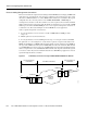
Table Of Contents
- Rules for Adding a DAX Connection
- Rules for Adding Three-Segment Connections
- Rules for Adding Management Connections
- BPX 8600-to-BPX 8600 Segment
- Very High Speed Frame Service Modules
- Eight-Port Channelized and Unchannelized Frame Service Module
- Four-Port Unchannelized Frame Service Module for V.35
- MGX-FRSM-2CT3 Features
- MGX-FRSM-2T3E3 Features
- MGX-FRSM-HS2/B Features
- MGX-FRSM-HS1/B Features
- Eight-Port FRSM Features
- Congestion Indication for NIW Connections
- PVC Status Management
- Cell Loss Priority
- Congestion Indication
- Command and Response Mapping
- Translation and Transparent Modes
- Loss Priority Indication
- Congestion Indication
- Cell Delay Treatment
- Error and Alarm Response
- Configuring the Card, Lines, and Ports
- Adding and Modifying Connections
- Configuring the Card, Lines, and Ports
- Configuring Bulk Distribution and Redundancy
- Adding and Modifying Connections
- Configuring Redundancy Through the Redundancy Bus
- Configuring Redundancy Through the Distribution Bus
- Pattern Test Options
- Loopback Test Options

Card and Service Configuration 6-5
The Processor Switching Module
The Processor Switching Module
This section first describes how to activate and configure the card-level parameters, lines, and ports
on the PXM uplink card then describes how to add connections to the PXM in a stand-alone node.
The descriptions tell you how to:
• Optionally modify the resource partitioning at the card level.
• Activate a line on the uplink card. On a stand-alone node, you can activate more than one line if
the uplink card has multiple lines. One physical line must be the trunk to a network routing node.
• If the switch has a pair of SRMs for bulk distribution and you use the CLI rather than the
CiscoView application, activate the SRM lines from the PXM.
• Optionally modify the resource partitioning at the port level.
• Create logical ports.
• On a stand-alone node, specify the cell header type. UNI cell headers typically apply where a
workstation connects to a UNI port on the uplink card rather than a port on the PXM-UI card.
Such an implementation is not common.
• On a stand-alone node, add standard connections and optional management connections.
• On a stand-alone node, configure Automatic Protection Switching (APS).
• For a feeder, execute steps on the connected BPX 8600-series switch to make the feeder an
available resource in the network.
Note For a description of the bit error rate test (BERT) functions, see the section titled “Bit Error
Rate Testing Through an MGX-SRM-3T3.”