CH A P T E R 2 Switch Installation This chapter describes how to start your switch and how to interpret the power-on self-test (POST) that ensures proper operation. It also describes how to install the switch.
Chapter 2 Switch Installation Preparing for Installation Warning Read the wall-mounting instructions carefully before beginning installation. Failure to use the correct hardware or to follow the correct procedures could result in a hazardous situation to people and damage to the system. Statement 378 Warning Do not work on the system or connect or disconnect cables during periods of lightning activity.
Chapter 2 Switch Installation Preparing for Installation Warning For connections outside the building where the equipment is installed, the following ports must be connected through an approved network termination unit with integral circuit protection: 10/100/1000 Ethernet.
Chapter 2 Switch Installation Powering the Switch • Temperature around the unit does not exceed 113°F (45°C). If the switch is installed in a closed environment or in a multirack assembly, the temperature around it might be greater than normal room temperature. • Humidity around the switch must not exceed 95 percent. • Altitude at the installation site must not be greater than 10,000 feet (3,049 meters). • Do not place any items on the top of the switch.
Chapter 2 Switch Installation Verifying Switch Operation You can use both the uplink port and the auxiliary power adapter. However, the auxiliary power input takes precedence. Note Catalyst 3560CPD-8PT-S • Connect a 10/100/1000 uplink port to a PoE+ switch, such as a Catalyst 3750-X. Or • Note Plug the auxiliary power adapter cord into the switch AUX power connector and into an AC power outlet. You can use both the uplink port and the auxiliary power adapter.
Chapter 2 Switch Installation Mounting the Switch On a Desk or Shelf (without Mounting Screws) Step 1 Locate the adhesive strip with the rubber feet in the accessory kit. Step 2 Remove the four rubber feet from the adhesive strip, and attach them to the recessed areas on the bottom of the unit. This prevents the switch from sliding on the desk or shelf. Note Step 3 Warning We strongly recommend that you attach the rubber feet. Doing so helps prevent airflow restriction and overheating.
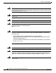
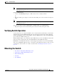
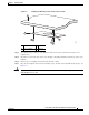
Chapter 2 Switch Installation Mounting the Switch Figure 2-1 Installing the Mounting Screws on Top of a Desk or a Shelf 2 3 210096 1 1 Screw template 3 2 Screws Desk or shelf Step 3 Peel the adhesive strip off the bottom of the screw template, and attach it to the top of the desk or shelf. Step 4 Use a 0.144-inch (3.7 mm) or a #27 drill bit to drill a 1/2-inch (12.7 mm) hole in the three screw template slots.
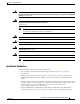
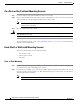
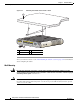
Chapter 2 Switch Installation Mounting the Switch Figure 2-2 Mounting the Switch on Top of a Desk or Shelf SYST STAT SPD 1 2 PoE CONSOL E 3 4 5 PD POWER OVER ETH ERNET Series PD 6 7 8 282394 DPLX MODE 1 2 3 1 2 1 Slides on this way 3 2 Screws Desk or shelf After you mount the switch, see the “After Installing the Switch” section on page 2-31 for information about configuring the switch.
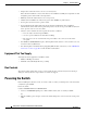
Chapter 2 Switch Installation Mounting the Switch Figure 2-3 Installing the Mounting Screws Under a Desk or Shelf 1 2 3 1 Desk or shelf 3 Screws 2 Screw template 4 Adhesive 250146 4 3 Step 4 Use a 0.144-inch (3.7 mm) or a #27 drill bit to drill a 1/2-inch (12.7 mm) hole in the three screw template slots. Step 5 Insert three screws in the slots on the screw template, and tighten until they touch the top of the screw template.
Chapter 2 Switch Installation Mounting the Switch Figure 2-4 Mounting the Switch Under a Desk or Shelf 1 282395 2 2 1 ERNET POWER CONSOL OVER ETH E PD 4 PoE MODE SPD DPLX 1 2 3 5 6 8 7 Catalyst 2960-C Series PD STAT SYST 3 1 Desk or shelf 2 Screws 3 Slides on this way After you mount the switch, see the “After Installing the Switch” section on page 2-31 for information about configuring the switch.
Chapter 2 Switch Installation Mounting the Switch Step 1 Locate the screw template. The template is used to align the mounting screw holes. Note Step 2 Figure 2-5 shows the measurements for the location of the screws on the switch. Position the screw template so that the two side-by-side slots face toward the floor, as shown in Figure 2-6. For the best support of the switch and cables, make sure that you attach the switch securely to a wall stud or to a firmly attached plywood mounting backboard.
Chapter 2 Switch Installation Mounting the Switch Figure 2-6 Installing the Mounting Screws on the Wall 1 2 THIS SID E MOUNT AWAY FROM ING SU RFACE SIDE EN TRY 157828 CABLE 2 3 2 Figure 2-7 Installing the Switch on a Wall 1 2 2 Step 8 2 208926 R E S E T U A X V 53 ,1 A .5 3 Place the switch onto the mounting screws, and slide it down until it locks in place. See Figure 2-7.
Chapter 2 Switch Installation Mounting the Switch With a Mounting Tray The mounting kit (part number CMP-MGNT-TRAY=) is optional. You can order it when you order your switch, or you can order it later from your Cisco representative. The mounting kit ships contents: • Two number-10 Phillips pan-head screws • Three number-8 Phillips pan-head screws • Mounting tray • Magnet You can use the mounting tray by itself with mounting screws, or with a magnet.
Chapter 2 Switch Installation Mounting the Switch Number-8 Phillips pan-head screws 2 Mounting tray 3 Desk or shelf Place the switch onto the mounting screws, and slide the switch until it locks into place. See Figure 2-9.
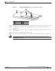
Chapter 2 Switch Installation Mounting the Switch Step 5 Use the two number-10 Phillips pan-head screws to secure the mounting tray to the switch. See Figure 2-10. Figure 2-10 Securing the Mounting Tray to the Switch 282397 1 SYST STAT DPLX 1 SPD MODE 2 PoE CONSOL E 3 4 PD POWER 5 Series 6 7 PD 8 OVER ETH ERNET 1 2 2 1 Warning 2 Switch Number-10 Phillips pan-head screws To prevent airflow restriction, allow clearance around the ventilation openings to be at least: 3 in. (7.
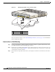
Chapter 2 Switch Installation Mounting the Switch Place the switch on the mounting tray. See Figure 2-11. Figure 2-11 Placing the Switch on the Mounting Tray 282398 Step 1 SYST STAT DPLX 1 SPD MODE 2 3 PoE 4 5 PD CONSOL E POWER OVER ETHERN 6 Series PD 7 8 ET 1 2 1 2 1 Step 2 2 Switch Mounting tray Use the two number-10 Phillips pan-head screws to secure the mounting tray to the switch. See Figure 2-12.
Chapter 2 Switch Installation Mounting the Switch Warning Read the wall-mounting instructions carefully before beginning installation. Failure to use the correct hardware or to follow the correct procedures could result in a hazardous situation to people and damage to the system. Statement 378 Caution Do not wall-mount the switch with its front panel facing up.
Chapter 2 Switch Installation Mounting the Switch In a Rack Installing the switch in a rack requires an optional bracket kit that is not included with the switch. You can order these kits from your Cisco representative: Warning • 19-inch rack-mounting brackets (RCKMNT-19-CMPCT=) • 23- and 24-inch rack-mounting brackets (RCKMNT-23-CMPCT=) To prevent bodily injury when mounting or servicing this unit in a rack, you must take special precautions to ensure that the system remains stable.
Chapter 2 Switch Installation Mounting the Switch Figure 2-15 shows how to attach a 23-inch bracket to one side of the switch. Follow the same steps to attach the second bracket to the opposite side.
Chapter 2 Switch Installation Mounting the Switch On a DIN Rail The DIN-mount kit (part number CMP-DIN-MNT=) is optional. You can order it when you order your switch, or you can order it later from your Cisco representative.
Chapter 2 Switch Installation Mounting the Switch Step 2 Use the two number-10 Phillips pan-head screws to secure the DIN rail mount to the switch. See Figure 2-18.
Chapter 2 Switch Installation Mounting the Switch Figure 2-19 Mounting the Switch on a DIN Rail 344214 T E S E R X U A 53 V ,1 .5 A 1 1 Switch Step 2 Rotate the switch down toward the DIN rail until the release tabs on the DIN rail mount clicks. Step 3 Lift lightly on the bottom of the switch to ensure that it is firmly locked in place. After you install the switch, see the “After Installing the Switch” section on page 2-31 for information about the switch configuration.
Chapter 2 Switch Installation Mounting the Switch Removing the Switch from a DIN Rail Step 1 Ensure that power is removed from the switch, and disconnect all cables and connectors from the front panel of the switch. Step 2 Pull down on the DIN rail mount release tabs. As the clips release, lift the bottom of the switch. See Figure 2-20. Figure 2-20 Switch Removal 344246 T E S E R X U A 53 V ,1 .
Chapter 2 Switch Installation Installing a Cover for the Reset Button (Optional) Installing a Cover for the Reset Button (Optional) You can cover the reset button to prevent accidental or unauthorized reset of your switch. To install a cover on the reset button: 1. Locate the cover (in the accessory kit). 2. Remove the adhesive sticker from the back of the cover. 3. Apply the cover on the switch. See Figure 2-21 and Figure 2-22 as examples. You can apply the cover to other switch models as well.
Chapter 2 Switch Installation Installing the Power Cord Retainer (Optional) Installing the Power Cord Retainer (Optional) Note This section applies to switches with an AC power connector. The power cord retainer part number (PWR-CLP=) is optional. You can order it when you order your switch, or you can order it later from your Cisco representative. Step 1 Choose the sleeve size of the power cord retainer based on the thickness of the cord. The smaller sleeve can be snapped off and used for thin cords.
Chapter 2 Switch Installation Installing the Power Cord Retainer (Optional) Step 3 Slide the retainer through the first latch. See Figure 2-24. Figure 2-24 Sliding the Retainer Through the Latch RESET 208985 1 3 2 Step 4 1 AC power cord 3 2 Smaller sleeve for thin power cords Latch Slide the retainer through the other latches to lock it. See Figure 2-25.
Chapter 2 Switch Installation Installing the Power Cord Retainer (Optional) Figure 2-26 Sleeve Around the Power Cord 2 1 208987 1 1 Step 6 2 Sleeve for thin power cords AC power cord Secure the AC power cord by pressing on the retainer. See Figure 2-27.
Chapter 2 Switch Installation Installing the Cable Guard (Optional) Installing the Cable Guard (Optional) The cable guard prevents tampering with the cables after the cables are installed. The cable guard (CMP-CBLE-GRD=) is not included with the switch, but you can order it from your Cisco representative. Note You can use the cable guard when the switch is mounted on a desk, under a desk, or on a wall. The cable guard is shipped with these items: Step 1 • Two 0.5 in. (12.
Chapter 2 Switch Installation Installing the Cable Guard (Optional) Step 2 Use the supplied number-10 pan-head screws to attach the cable guard to the switch. See Figure 2-29.
Chapter 2 Switch Installation Installing the Cable Guard (Optional) Figure 2-31 Attaching the Cables to the Switch 2 SYST STAT SPD 1 2 PoE PD CONSOL E POWER OVER 3 4 Catalyst 5 6 7 ETHERN ET 2960-C Series PD 8 1 208918 DPLX MODE 2 1 1 Step 4 2 Cable guard Pivot direction for cable guard pivots Guide the connected cables through the slots in the front of the cable guard. Slide the cable guide in as shown in Figure 2-33. Tighten the screws.
Chapter 2 Switch Installation After Installing the Switch Step 5 (Optional) To attach the cable guard to the desk or wall, use a 0.144-inch (3.7 mm) or a #27 drill bit to drill 1/2-inch (12.7 mm) holes at each of the two mounting locations. Insert the supplied 0.5 in. (12.7 mm) number-8 Phillips wood screws and tighten them as shown in Figure 2-33. Figure 2-33 Securing the Cable Guard to the Desk 1 208919 1 2 1 Number-8 Phillips wood screws 2 Desk or shelf After Installing the Switch 1.
Chapter 2 Switch Installation Removing SFP Modules Warning Class 1 laser product. Statement 1008 Step 1 Attach an ESD-preventive wrist strap to your wrist and to a bare metal surface. Step 2 Find the send (TX) and receive (RX) markings on the module top. On some SFP modules, the TX and RX markings might be replaced by arrows that show the direction of the connection, either send or receive. Step 3 If the module has a bale-clasp latch, move it to the open, unlocked position.
Chapter 2 Switch Installation Connecting Devices to the Ethernet Ports Figure 2-35 Removing a Bale-Clasp Latch SFP Module Catalys t 3560 5 6 7 -CG Ser ies PoE 8 9 208914 10 1 1 Bale clasp Connecting Devices to the Ethernet Ports • Connecting to the 10/100 and 10/100/1000 Ports, page 2-33 • Connecting to the PoE Ports, page 2-34 Connecting to the 10/100 and 10/100/1000 Ports The 10/100 and 10/100/1000 Ethernet ports use RJ-45 connectors with Ethernet pinouts.
Chapter 2 Switch Installation Connecting Devices to the Ethernet Ports Figure 2-36 Connecting to an Ethernet Port Catalys t 2960 5 6 7 -C Serie s PD 8 1 208915 2 Table 2-1 Ethernet Cables (Auto-MDIX Disabled) Device Crossover Cable1 Straight-Through Cable1 Switch to switch Yes No Switch to hub Yes No Switch to computer or server No Yes Switch to router No Yes Switch to IP phone No Yes 1.
Chapter 2 Switch Installation Where to Go Next restricted access location and users and service people who are authorized within the restricted access location are made aware of the hazard. A restricted access area can be accessed only through the use of a special tool, lock and key or other means of security. Statement 1072 Caution Category 5e and Category 6 cables can store high levels of static electricity.
Chapter 2 Switch Installation Where to Go Next Catalyst 3560-C and 2960-C Switch Hardware Installation Guide 2-36 OL-23803-02