
User manual


9-6 LightStream 1010 ATM Switch PAM Installation Guide
Configuring the Interfaces
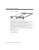
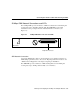
25 Mbps Module LEDs
The LEDs provide status information for the port adapter module’s individual 25-Mbps
interface connections. The LEDs are shown in Figure 9-3 and described in Table 9-1.
Configuring the Interfaces
When the switch is powered on initially without any previous configuration data, the ATM
interfaces are automatically configured on the physical ports. ILMI and the physical card
type are used to automatically derive the ATM interface type, UNI version, maximum
virtual path identifier (VPI) and virtual channel identifier (VCI) bits, ATM interface side,
and ATM UNI type.
When you hot-swap a CM or PAM, the configuration for the initially installed PAM
interface configuration is saved. If the same type of PAM is reinstalled, no additional
configuration is needed. The initial configuration is reestablished.
The interface configuration is described in the section “Default ATM Interface
Configuration Without Autoconfiguration.”
Table 9-1 25-Mbps PAM LED Descriptions
LED Description
(Receive) Off—No receive line activity
Flashing green—Cells being received: blinks every five seconds and pulse
rate increases with data rate
Flashing yellow—Loopback
Steady yellow—Alarm FERF
1
Red—Alarm (Line Code Error or LCD
2
)
1. FERF = far-end receive failure
2. LCD = loss of cell delineation