Installation and Upgrade Guide for Cisco Unified Videoconferencing 3545 PRI Gateway and 3545 Serial Gateway Release 5.5 January 2008 Americas Headquarters Cisco Systems, Inc. 170 West Tasman Drive San Jose, CA 95134-1706 USA http://www.cisco.
THE SPECIFICATIONS AND INFORMATION REGARDING THE PRODUCTS IN THIS MANUAL ARE SUBJECT TO CHANGE WITHOUT NOTICE. ALL STATEMENTS, INFORMATION, AND RECOMMENDATIONS IN THIS MANUAL ARE BELIEVED TO BE ACCURATE BUT ARE PRESENTED WITHOUT WARRANTY OF ANY KIND, EXPRESS OR IMPLIED. USERS MUST TAKE FULL RESPONSIBILITY FOR THEIR APPLICATION OF ANY PRODUCTS.
CONTENTS CHAPTER 1 Functionality 1-1 About Cisco Unified Videoconferencing 3545 Gateway Products 1-1 About the Cisco Unified Videoconferencing 3545 PRI Gateway 1-1 About the Cisco Unified Videoconferencing 3545 Serial Gateway 1-1 About Gateway Features 1-2 About Cisco Unified Videoconferencing 3545 Gateway Applications and Topologies About Multimedia Conferencing 1-7 About Point-to-Point Conferencing 1-8 About Multipoint Conferencing 1-8 About Gateway IP Network Connections 1-9 About Gateway ISDN Netw
Contents Setting the IP Address 2-11 Changing the Configuration Tool Login Password Upgrading Gateway Software 2-13 Connecting the Gateway to the Network Connecting PRI Lines to the Gateway 2-12 2-14 2-14 Connecting Serial Lines to the Gateway 2-14 Serial Gateway Cable Connections and Pin-outs 2-15 Physical Description of DTE Cables 2-15 Physical Description of DCE Cables 2-19 Data Interface Cable Pin-out Configurations 2-21 Data Interface Pin Layouts 2-22 DB-25 Connector 2-24 Signaling Interface Cab
Contents High Voltage 6-2 Power Supply 6-2 ESD Procedures Sicherheit 6-2 6-3 Elektrische Sicherheit 6-3 Erdung 6-3 Hochspannung 6-3 Netzteil 6-3 ESD-Verfahren 6-4 Warnhinweise 6-4 Seguridad 6-5 Seguridad Electrica 6-5 Tierra 6-5 Alto Voltage 6-5 Abastecimiento de Electricidad Procedimientos ESD Securite 6-5 6-6 6-7 Securite Electrique 6-7 Mise a la Terre 6-7 Haute Tension 6-8 Alimentation Electrique 6-8 Prevention des Decharges Electrostatiques CHAPTER 7 Compliance and Certifications Safe
Contents Installation and Upgrade Guide for Cisco Unified Videoconferencing 3545 PRI Gateway and 3545 Serial Gateway Release 5.
CH A P T E R 1 Functionality This section describes the following topics: • About Cisco Unified Videoconferencing 3545 Gateway Products, page 1-1 • About Gateway Features, page 1-2 • About Cisco Unified Videoconferencing 3545 Gateway Applications and Topologies, page 1-6 • About Cisco Unified Videoconferencing 3545 Gateway Functionality, page 1-13 About Cisco Unified Videoconferencing 3545 Gateway Products Cisco Unified Videoconferencing 3545 Gateway series consists of the following products: • C
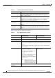
Chapter 1 Functionality About Gateway Features About Gateway Features Table 1-1 lists the major features of the Cisco Unified Videoconferencing 3545 Gateway. Table 1-1 Gateway Feature Summary Feature Description Interoperability The gateway provides a high degree of interoperability with other H.323 compliant gateways, gatekeepers, terminals, proxy, and Multipoint Control Unit (MCU) products by being based on the H.320 standard and H.323 protocol stack.
Chapter 1 Functionality About Gateway Features Table 1-1 Gateway Feature Summary (continued) Feature Description Access control The gateway features password-controlled access to the gateway interface. Up to ten different administrator access profiles can be defined for the gateway. DTMF translation The gateway supports translation between in-band Dual Tone Multi-Frequency (DTMF) signals (on the ISDN side) and out-of-band H.245 messages (on the IP side).
Chapter 1 Functionality About Gateway Features Table 1-1 Gateway Feature Summary (continued) Feature Description Encryption support The gateway supports H.235-compliant AES 128 encryption for calls over IP networks, and H.233 and H.234-compliant AES 128 encryption for calls over ISDN networks. H.243 Conference Control support The gateway supports the H.243 protocol in ISDN-to-IP calls and in IP-to-ISDN calls. The gateway identifies the protocol version that an IP endpoint uses and sends H.
Chapter 1 Functionality About Gateway Features Table 1-2 Cisco Gateway Feature Specifics (continued) Feature Cisco Unified Videoconferencing 3545 PRI Gateway Supported video resolutions VGA, XGA, SVGA, SIF, 4SIF, CIF, QCIF, 4CIF, 16CIF Supported bandwidths (Kbps) 56, 64, 112, 128, 168, 192, 224, 256, 56, 64, 112, 128, 168, 192, 224, 256, 280, 320, 336, 384, 448, 512, 672, 280, 320, 336, 384, 448, 512, 672, 768, 1288, 1472, 1680 and 1920 768, 1288, 1472 and 1920 Note Call handling capabilities Cis
Chapter 1 Functionality About Cisco Unified Videoconferencing 3545 Gateway Applications and Topologies Table 1-2 Cisco Gateway Feature Specifics (continued) Feature Cisco Unified Videoconferencing 3545 PRI Gateway Cisco Unified Videoconferencing 3545 Serial Gateway Supported media + signaling combinations N/A RS-449 + RS-366 V.35 + RS-366 EIA-530 + RS-366 EIA-530A + RS-366 Encryption interoperability N/A KIV-7, KG-194 PRI interface Configurable E1/T1 PRI network interface.
Chapter 1 Functionality About Cisco Unified Videoconferencing 3545 Gateway Applications and Topologies • Conferencing over leased lines (see the “About Conferencing via Leased Lines” section on page 1-12) • Communicating with legacy MCU equipment (see the “About IP-to-Legacy MCU Conferencing” section on page 1-12) About Multimedia Conferencing The Cisco PRI gateway enables H.323 endpoints on the IP network to communicate with an H.
Chapter 1 Functionality About Cisco Unified Videoconferencing 3545 Gateway Applications and Topologies About Point-to-Point Conferencing The Cisco PRI gateway enables direct video, voice, and data communication between an H.320 (ISDN) terminal and H.323 (IP) terminals at bandwidths of up to 1472 Kbps (23B bonding for T1) and up to 1920 Kbps (30B bonding for E1). Figure 1-2 Point-to-Point Conferencing through the Gateway H.323 terminal IP network ISDN Cisco chassis/unit with serial gateway H.
Chapter 1 Functionality About Cisco Unified Videoconferencing 3545 Gateway Applications and Topologies Figure 1-3 Mixed ISDN-IP Multipoint Multimedia Conference IP network H.323 Terminal IP IP phone H.323 Terminal H.320 Terminal Cisco IPVC chassis/unit ISDN H.323 Terminal Cisco IPVC Gateway Cisco IPVC MCU IP IP phone H.320 Terminal H.320 Terminal 92871 H.323 Terminal H.
Chapter 1 Functionality About Cisco Unified Videoconferencing 3545 Gateway Applications and Topologies PRI Gateways You can connect the PRI gateway directly to a PRI line provided by your local ISDN provider (as shown in Figure 1-4), or to a local private branch exchange (PBX) that provides the PRI connection (as shown in Figure 1-5). Figure 1-4 Connecting the PRI Gateway Directly to a Central Office Switch Private Public IP network Cisco IPVC chassis/unit PRI T1/E1 H.
Chapter 1 Functionality About Cisco Unified Videoconferencing 3545 Gateway Applications and Topologies About Gateway Encryption The serial gateway enables encrypted videoconferencing between H.323 endpoints on the IP network and endpoints on remote sites by connecting to external encryption/decryption devices via serial interfaces (as shown in Figure 1-6). The serial gateway also enables encrypted videoconferencing via satellite with or without RS-366 signaling (as shown in Figure 1-7).
Chapter 1 Functionality About Cisco Unified Videoconferencing 3545 Gateway Applications and Topologies About Conferencing via Leased Lines The serial gateway enables conferencing between H.323 endpoints on IP networks connected via a leased line (as shown in Figure 1-8). Figure 1-8 Conferencing via Leased Lines H.323 endpoint IP network IP network Adaptor V35. DCE DTE Cisco chassis/unit with serial gateway Cisco chassis/unit with serial gateway 157170 H.323 endpoint Adaptor Leased line V35.
Chapter 1 Functionality About Cisco Unified Videoconferencing 3545 Gateway Functionality About Cisco Unified Videoconferencing 3545 Gateway Functionality This section discusses the following topics: • About PRI Gateway Call Handling Capacity, page 1-13 • About Gateway Call Bandwidth Overhead, page 1-13 • About Peer-to-Peer Connectivity, page 1-14 About PRI Gateway Call Handling Capacity Table 1-3 lists the maximum call handling capacity of the PRI gateway for different types of calls.
Chapter 1 Functionality About Cisco Unified Videoconferencing 3545 Gateway Functionality Resource Allocation across E1/T1 Lines The gateway can allocate bandwidth resources to calls across separate E1 or T1 connections to maximize bandwidth capacity in cases where there is not enough capacity for a call on a single E1 or T1 connection, but where sufficient capacity does exist when remaining capacity on both E1/T1 lines is combined.
CH A P T E R 2 Installing the Cisco Unified Videoconferencing 3545 Gateway This section describes the following topics: • Physical Description, page 2-1 • Preparing for Installation, page 2-3 • Verifying the Package Contents, page 2-4 • Mounting the Cisco Unified Videoconferencing 3545 Chassis in a 19-inch Rack, page 2-5 • Installing the Gateway, page 2-6 • Initial Gateway Configuration, page 2-10 • Connecting the Gateway to the Network, page 2-14 • Connecting PRI Lines to the Gateway, page
Chapter 2 Installing the Cisco Unified Videoconferencing 3545 Gateway Physical Description Gateway Front Panel GK Reg CD SERIAL RST 10/100Base T-1 Table 2-1 157269 Figure 2-1 SWAP RDY ALARM ACT Front Panel Components Component Description 10/100 Base T-1 connector An RJ-45 connector that provides the primary Ethernet connection for the IP network port. SERIAL connector A DB-9 connector that allows you to connect a PC terminal for local configuration.
Chapter 2 Installing the Cisco Unified Videoconferencing 3545 Gateway Preparing for Installation Table 2-2 PRI Gateway Rear Transition Module Components (continued) Component Description ALARM LEDs Displays alarm events for the PRI line. PRI LINE connectors • YELLOW —Lights yellow when there is a loss of frame alignment at the remote side. • ORANGE—Lights orange when there is a loss of frame alignment in the gateway.
Chapter 2 Installing the Cisco Unified Videoconferencing 3545 Gateway Verifying the Package Contents • A PC with a serial port and terminal emulation software to assign the gateway an IP address • Dedicated IP address for the gateway • The IP address of the router the gateway will use to communicate across the network • The IP address of the H.
Chapter 2 Installing the Cisco Unified Videoconferencing 3545 Gateway Mounting the Cisco Unified Videoconferencing 3545 Chassis in a 19-inch Rack Related Topics • Serial Gateway Cable Connections and Pin-outs, page 2-15 Mounting the Cisco Unified Videoconferencing 3545 Chassis in a 19-inch Rack You can optionally mount the Cisco Unified Videoconferencing 3545 chassis in a standard 19-inch rack.
Chapter 2 Installing the Cisco Unified Videoconferencing 3545 Gateway Installing the Gateway Installing the Gateway This section describes how to insert a gateway into the Cisco Unified Videoconferencing 3545 chassis. Before You Begin Note the following: • The Cisco Unified Videoconferencing 3545 chassis has four slots. You can install the Cisco Unified Videoconferencing 3545 Gateway in any of the slots.
Chapter 2 Installing the Cisco Unified Videoconferencing 3545 Gateway Installing the Gateway Installing the RTM Module This section describes how to install the RTM module in the Cisco Unified Videoconferencing 3545 chassis. The Rear Transition Module (RTM) provides the ISDN or serial line connections for the gateway. Warning You must install the RTM module before you install the gateway module.
Chapter 2 Installing the Cisco Unified Videoconferencing 3545 Gateway Installing the Gateway Blank faceplates and cover panels serve three important functions: they prevent exposure to hazardous voltages and currents inside the chassis; they contain electromagnetic interference (EMI) that might disrupt other equipment; and they direct the flow of cooling air through the chassis. Do not operate the system unless all cards, faceplates, front covers, and rear covers are in place.
Chapter 2 Installing the Cisco Unified Videoconferencing 3545 Gateway Installing the Gateway Blank faceplates and cover panels serve three important functions: they prevent exposure to hazardous voltages and currents inside the chassis; they contain electromagnetic interference (EMI) that might disrupt other equipment; and they direct the flow of cooling air through the chassis. Do not operate the system unless all cards, faceplates, front covers, and rear covers are in place.
Chapter 2 Installing the Cisco Unified Videoconferencing 3545 Gateway Initial Gateway Configuration Step 5 Insert a blank cover panel provided by Cisco. Step 6 Secure the blank cover panel screws. Caution Blank faceplates and cover panels serve three important functions: they prevent exposure to hazardous voltages and currents inside the chassis; they contain electromagnetic interference (EMI) that might disrupt other equipment; and they direct the flow of cooling air through the chassis.
Chapter 2 Installing the Cisco Unified Videoconferencing 3545 Gateway Initial Gateway Configuration Setting the IP Address This section describes how to use the serial port to configure the unit with an IP address and other address information. The serial port on the gateway front panel is used to assign a new IP address to your gateway. You must assign the IP address before you connect the gateway to the network.
Chapter 2 Installing the Cisco Unified Videoconferencing 3545 Gateway Initial Gateway Configuration The network configuration Main menu displays: Press any Main menu Enter Enter Enter Enter Caution Key To start configuration...
Chapter 2 Installing the Cisco Unified Videoconferencing 3545 Gateway Initial Gateway Configuration Step 7 Type the password you want the user to use to log in to the gateway interface and press Enter. There is no default password. Step 8 The network configuration Main menu re-appears. Step 9 Enter Q and press Enter to exit.
Chapter 2 Installing the Cisco Unified Videoconferencing 3545 Gateway Connecting the Gateway to the Network Connecting the Gateway to the Network The Cisco Unified Videoconferencing 3545 Gateway can connect to the LAN only through the front panel. The gateway supports a 10/100BaseT, full-duplex Ethernet interface through an RJ-45 connector. Procedure Step 1 Connect the supplied LAN cable from your network hub to the 10/100BaseT Ethernet port on the front panel of the gateway.
Chapter 2 Installing the Cisco Unified Videoconferencing 3545 Gateway Serial Gateway Cable Connections and Pin-outs Serial Gateway Cable Connections and Pin-outs This section describes the DTE and DCE cables that you can use with the Cisco Cisco Unified Videoconferencing 3545 Serial Gateway including the following topics: • Physical Description of DTE Cables, page 2-15 • Physical Description of DCE Cables, page 2-19 • Data Interface Cable Pin-out Configurations, page 2-21 • Data Interface Pin Layou
Chapter 2 Installing the Cisco Unified Videoconferencing 3545 Gateway Serial Gateway Cable Connections and Pin-outs V.35/RS366-DTE Figure 2-7 shows the V.35/RS366-DTE cable. Figure 2-7 V.35/RS366-DTE Cable J2 Male (M-34 Winchester) V.35 data RS-366 signaling 157179 J1 Male (DB-60) J3 Male (DB-25) EIA449/RS366-DTE Figure 2-8 shows the EIA449/RS366-DTE cable.
Chapter 2 Installing the Cisco Unified Videoconferencing 3545 Gateway Serial Gateway Cable Connections and Pin-outs EIA530/RS366-DTE Figure 2-9 shows the EIA530/RS366-DTE cable. Figure 2-9 EIA530/RS366-DTE Cable J2 Male (DB-25) EIA-530 data RS-366 signaling 157160 J1 Male (DB-60) J3 Male (DB-25) EIA530/RS366-DTE-LOS Figure 2-10 shows the EIA530/RS366-DTE-LOS cable.
Chapter 2 Installing the Cisco Unified Videoconferencing 3545 Gateway Serial Gateway Cable Connections and Pin-outs EIA530A/RS366-DTE Figure 2-11 shows the EIA530A/RS366-DTE cable. Figure 2-11 EIA530A/RS366-DTE Cable J2 Male (DB-25) J1 Male (DB-60) EIA-530A data 157162 RS-366 signaling J3 Male (DB-25) KIV7/RS366-DTE Figure 2-12 shows the KIV7/RS366-DTE cable.
Chapter 2 Installing the Cisco Unified Videoconferencing 3545 Gateway Serial Gateway Cable Connections and Pin-outs Physical Description of DCE Cables This section describes the following DCE cables supplied with the Cisco Cisco Unified Videoconferencing 3545 Serial Gateway: Note • V.35/RS366-DCE, page 2-19 • EIA449/RS366-DCE, page 2-20 • EIA530/RS366-DCE, page 2-20 • The DB-25 connector provides the data interface for the EIA530/RS366-DCE cable.
Chapter 2 Installing the Cisco Unified Videoconferencing 3545 Gateway Serial Gateway Cable Connections and Pin-outs EIA449/RS366-DCE Figure 2-14 shows the EIA449/RS366-DCE cable. Figure 2-14 EIA449/RS366-DCE Cable J2 Female (DB-37) EIA-449 data RS-366 signaling 157157 J1 Male (DB-60) J3 Female (DB-25) EIA530/RS366-DCE Figure 2-15 shows the EIA530/RS366-DCE cable.
Chapter 2 Installing the Cisco Unified Videoconferencing 3545 Gateway Serial Gateway Cable Connections and Pin-outs Data Interface Cable Pin-out Configurations Table 2-7 describes the data interface pin-out configuration for the serial gateway cables. Signal Name Mnemonic EIA-449 (DB-37) EIA-530 (DB-25) EIA-530 LOS (DB-25) DTE only EIA-530A LOS (DB-25) DTE only V.
Chapter 2 Installing the Cisco Unified Videoconferencing 3545 Gateway Serial Gateway Cable Connections and Pin-outs Data Interface Pin Layouts This section illustrates the pin layouts for the serial gateway cable connectors. M-34 Connector Figure 2-16 shows the M-34 pin assignment.
Chapter 2 Installing the Cisco Unified Videoconferencing 3545 Gateway Serial Gateway Cable Connections and Pin-outs DB-37 Connector Figure 2-17 shows the DB-37 pin layout. Figure 2-17 20 21 DB-37 Pin Layout 1 2 3 22 4 23 5 24 6 25 7 26 8 27 9 28 10 29 11 30 12 31 13 33 34 35 36 37 14 15 16 17 18 19 157147 32 Installation and Upgrade Guide for Cisco Unified Videoconferencing 3545 PRI Gateway and 3545 Serial Gateway Release 5.
Chapter 2 Installing the Cisco Unified Videoconferencing 3545 Gateway Serial Gateway Cable Connections and Pin-outs DB-25 Connector Figure 2-18 shows the DB-25 pin layout. Figure 2-18 DB-25 Pin Layout 1 14 2 15 3 16 4 17 5 18 6 19 7 20 8 21 9 22 10 23 11 24 12 13 157145 25 Installation and Upgrade Guide for Cisco Unified Videoconferencing 3545 PRI Gateway and 3545 Serial Gateway Release 5.
Chapter 2 Installing the Cisco Unified Videoconferencing 3545 Gateway Serial Gateway Cable Connections and Pin-outs Signaling Interface Cable Pin-out Configuration Table 2-8 describes the signaling interface pin-out configuration for the serial gateway cables.
Chapter 2 Installing the Cisco Unified Videoconferencing 3545 Gateway Serial Gateway Cable Connections and Pin-outs Signaling Interface Pin Layout This section illustrates the pin layout for the serial gateway signaling cable connector. DB-25 Connector Figure 2-19 shows the DB-25 pin layout.
Chapter 2 Installing the Cisco Unified Videoconferencing 3545 Gateway Connecting the Gateway to a Power Source Connecting the Gateway to a Power Source This section describes how to supply power to the gateway. The gateway is equipped with an autoswitching power supply that supports 100-240 VAC at 50/60 Hz. Warning Never defeat the ground conductor or operate the equipment in the absence of a suitably installed ground conductor.
Chapter 2 Installing the Cisco Unified Videoconferencing 3545 Gateway Registering the Online Help Step 2 Type the Administrator user name and password in the appropriate fields and click Login. The default global user name is admin. The default password is . Note If you try to sign in as an Administrator and another Administrator is currently signed in, the gateway signs you in as a Read only user and the words Read Only appear at the top of the window.
CH A P T E R 3 Using the Cisco Software Upgrade Utility This section describes the following topics: • Introduction, page 3-1 • Launching the Cisco Software Upgrade Utility, page 3-1 • Upgrading Software, page 3-2 Introduction The Cisco Software Upgrade Utility is an interactive GUI interface that enables you to upgrade Cisco software installed on Cisco devices. The Cisco Software Upgrade Utility enables you to select files to be uploaded via a network or modem connection to the Cisco device.
Chapter 3 Using the Cisco Software Upgrade Utility Upgrading Software Upgrading Software This section describes how to use the Software Upgrade Utility to upgrade Cisco software installed on Cisco devices. Procedure Step 1 In the General Information section of the Upgrade Utility dialog box, enter the IP address of the device you want to upgrade.
CH A P T E R 4 Cable Connections and Pin-outs This section describes the following topics: • Unit RS-232 9-Pin Serial Port, page 4-1 • 9-Pin Serial Port Terminal Cable, page 4-2 • RJ-45 8-Pin IP Network Port, page 4-2 • Circuit Switch Network Port, page 4-3 • ISDN Port, page 4-3 Unit RS-232 9-Pin Serial Port Table 4-1 describes the Cisco Unified Videoconferencing 3545 chassis RS-232 9-pin D-type serial port pin-out configuration.
Chapter 4 Cable Connections and Pin-outs 9-Pin Serial Port Terminal Cable 9-Pin Serial Port Terminal Cable Table 4-2 describes the pin-to-pin configuration of the RS-232 terminal cable provided with the Cisco Unified Videoconferencing 3545 chassis. Table 4-2 S-232 Terminal Cable Pin-to-Pin Configuration To Chassis (DB-9 Male) Function To PC Terminal (DB-9 Female) 2 TXD 3 3 RXD 2 5 GND 5 RJ-45 8-Pin IP Network Port Table 4-3 describes the pin-out configuration of the RJ-45 IP network port.
Chapter 4 Cable Connections and Pin-outs Circuit Switch Network Port Circuit Switch Network Port Table 4-4 describes the circuit switch network port RJ-45 connector pin-out configuration. Table 4-4 Circuit Switch Network Port RJ-45 Connector Pin-out Pin Function 1 RXD + 2 RXD - 3 NC 4 TXD + 5 TXD - 6 NC 7 NC 8 NC ISDN Port Table 4-5 describes the ISDN Port RJ-45 connector pin-out configuration.
Chapter 4 Cable Connections and Pin-outs ISDN Port Installation and Upgrade Guide for Cisco Unified Videoconferencing 3545 PRI Gateway and 3545 Serial Gateway Release 5.
CH A P T E R 5 Technical Specifications This section provides technical specifications for the Cisco Unified Videoconferencing 3545 Chassis. Technical Specifications Table Table 5-1 Cisco Unified Videoconferencing 3545 Chassis Technical Specifications Chassis Dimensions • Height: 2U (3.5 inches or 88.9 mm) • Width: 17.25 inches (438.15 mm) • Depth: 10 inches (254 mm) • Weight: 8 kg (17.64 lbs) empty, 11 kg (24.
Chapter 5 Technical Specifications Technical Specifications Table Table 5-1 Cisco Unified Videoconferencing 3545 Chassis Technical Specifications (continued) Board LED Indicators Front panel Rear panel (Cisco Unified Videoconferencing 3545 PRI Gateway) • ETHERNET: • Link • Connection Speed • GK Reg • CPU High (MCU only) • CD (gateways only) • ALARM • ACT • MC (EMP only) • PRI 1 or 2: Rear panel (Cisco Unified Videoconferencing 3545 Serial Gateway) • Push Buttons • • ACT • D-
Chapter 5 Technical Specifications Technical Specifications Table Table 5-1 Cisco Unified Videoconferencing 3545 Chassis Technical Specifications (continued) Rear panel (Cisco Unified Videoconferencing 3545 Serial Gateway) • 4 x serial ports Chipset • PowerPC MPC7410 32-bit RISC microprocessor running at 500MHz. • MPC8260 communication processor running at 300/200MHz. Operating System • RTOS, VxWorks 5.
Chapter 5 Technical Specifications Technical Specifications Table Installation and Upgrade Guide for Cisco Unified Videoconferencing 3545 PRI Gateway and 3545 Serial Gateway Release 5.
CH A P T E R 6 Safety This section describes the following topics: • Electrical Safety, page 6-1 • ESD Procedures, page 6-2 Electrical Safety To avoid an electric shock or damage to the Cisco Unified Videoconferencing 3545 System, servicing should be performed by qualified service personnel only. To reduce the risk of damaging power surges, Cisco recommends installing an AC surge arrestor in the AC outlet from which the Cisco Unified Videoconferencing 3545 System is powered.
Chapter 6 Safety ESD Procedures Caution This is a class I unit. In Denmark, use this unit with an AC cord suited to Danish specifications. The cord should include an earthing conductor. Plug the unit into a wall socket outlet which is connected to the protective earth contact. Do not use socket outlets which are not connected to a protective earth contact! Laite on liitettävä suojamaadoituskoskettimilla varustettuun pistorasiaan. Apparatet må tilkoples jordet stikkontakt.
Chapter 6 Sicherheit Elektrische Sicherheit Sicherheit Dieses Kapitel beschreibt die Sicherheitsvorschriften und -vorgaben zur Bedienung der Cisco Unified Videoconferencing 3545-Plattform einschließlich des Folgenden: • Elektrische Sicherheit, page 6-3 • ESD-Verfahren, page 6-4 • Warnhinweise, page 6-4 Elektrische Sicherheit Zur Vermeidung eines elektrischen Schlags oder Schäden an der Cisco Unified Videoconferencing 3545-Plattform darf die Wartung von qualifiziertem Fachpersonal vorgenommen werden.
Chapter 6 Sicherheit ESD-Verfahren ESD-Verfahren Zur Vermeidung von Beschädigungen der Cisco Einsatzelemente durch zufällige elektrostatische Entladungen (ESD) wird die Verwendung von Schlaufen sehr empfohlen. Warnhinweise • Änderungen oder Modifikationen, die von der für die Einhaltung verantwortlichen Partei nicht ausdrücklich genehmigt sind, können die Erlaubnis zur Nutzung des Geräts durch den Benutzer unwirksam machen.
Chapter 6 Seguridad Seguridad Electrica Seguridad Seguridad Electrica Para prevenir un choque eléctrico o dañar la plataforma Cisco Unified Videoconferencing 3545, los servicios deben ser hechos solamente por personal de servicios calificados. Para reducir el riesgo de daño por picos de voltaje, Cisco recomienda la instalación de un supresor de voltaje para corriente alterna AC en el circuito del tomacorriente para la plataforma Cisco Unified Videoconferencing 3545.
Chapter 6 Seguridad Procedimientos ESD Procedimientos ESD Para prevenir daño a las tarjetas elementos de Cisco por descargas electrostáticas aleatorias (ESD), el uso de bandas conductoras para descarga en la muñeca de los operadores en el área es altamente recomendado. Installation and Upgrade Guide for Cisco Unified Videoconferencing 3545 PRI Gateway and 3545 Serial Gateway Release 5.
Chapter 6 Securite Securite Electrique Securite Cette section décrit les procédures et les exigences en matière de sécurité concernant la mise en exploitation de la Cisco Unified Videoconferencing 3545 System.
Chapter 6 Securite Prevention des Decharges Electrostatiques • En Suède et en Finlande, l’installation ne doit se faire que dans des zones à accès contrôlé. Haute Tension Débranchez le Cisco Unified Videoconferencing 3545 chassis de la prise électrique avant d’enlever le couvercle. Évitez toute intervention, opération d’entretien ou réparation sur un châssis ouvert sous tension. Ces actions ne devraient être effectuées que par une personne expérimentée et connaissant les dangers encourus.
CH A P T E R 7 Compliance and Certifications This section describes the following topics: • Safety Compliance, page 7-1 • EMC, page 7-2 • Telecom, page 7-2 • Environmental Compliance, page 7-4 Safety Compliance This section lists the safety standards supported by the Cisco Unified Videoconferencing 3545 System. • UL 60950 • CSA C22.2 No.
Chapter 7 Compliance and Certifications EMC EMC This section lists the EMC compliance for the Cisco Unified Videoconferencing 3545 System. Warning • FCC Part 15 (CFR 47) Class A • ICES-003 Class A • EN 55022 Class A • CISPR22 Class A • AS/NZS CISPR22 Class A • VCCI Class A • CISPR24 • EN 55024 • EN 50082-1 • EN 61000-3-2 • EN 61000-3-3 • EN 61000-6-1 This is a class A product.
Chapter 7 Compliance and Certifications Telecom ACTA Customer Information Step 1 This equipment complies with Part 68 of the FCC rules, and the requirement adopted by the ACTA. On the cover of this equipment is a label that contains, among other information, a product identifier in the format US:AAAEQ##TXXXX, made out to CLPISR-45023-DW-N. If requested, this information must be provided to the telephone company.
Chapter 7 Compliance and Certifications Environmental Compliance Users should ensure for their own protection that the ground connections of the power utility, telephone lines and internal metallic water pipe platform, are connected together. This precaution may be particularly important in rural areas. Warning Users should not attempt to make such connections themselves, but should contact the appropriate E1/T1/PRI electric inspection authority, or appropriate E1/T1/PRI electrician.
INDEX RJ-45 8-pin IP network port A RS-232 9-pin serial port access control ACT LED 1-3 V.35/RS366-DCE 2-19 2-2, 2-3 V.
Index downspeeding DTMF hot swap 1-3 1-3 1-3 dual video 1-3 I initial configuration E 2-10 installation procedures E1/T1 access Administrator interface 1-9, 1-14 EIA-530 change default password 2-14 element board dimensions EMC connect a serial cable 5-1 2-12 2-14 connect gateway to LAN 7-2 encryption connect to a PC 1-4 2-14 2-10 interoperability 1-6 connect to power supply 2-27 serial gateway 1-11 insert gateway in chassis 2-8 via satellite insert RTM in chassis 1-1
Index ISDN port RJ-45 connector M RJ-45 IP network port media + signaling combinations media protocols memory MSN 1-6 4-3 4-2 RS-232 9-pin D-type serial port 1-5 4-1 serial gateway data interface cable 5-3 2-21 serial gateway signaling interface cable 1-2 2-25 pin-to-pin configuration multimedia conferencing 1-7 multipoint conferencing RS-232 terminal cable 1-8 4-2 point-to-point conferencing PORT connectors 1-8 2-3 ports N RJ-45 IP Netscape Navigator RS-232 9-pin serial 2-28
Index RS-232 V DTE 9-pin D-type connection RS-449 V.