Cisco EtherSwitch Service Modules Feature Guide Note This document describes the Cisco EtherSwitch service module only. For information about the Cisco Ethernet switch network module, see “Connecting Ethernet Switch Network Modules to a Network” at the following URL: http://www.cisco.com/en/US/products/hw/modules/ps2797/products_module_installation_guide_chapt er09186a00800b168c.
Cisco EtherSwitch Service Modules Feature Guide Contents Finding Support Information for Platforms and Cisco IOS Software Images Use Cisco Feature Navigator to find information about platform support and Cisco IOS software image support. Access Cisco Feature Navigator at http://www.cisco.com/go/fn. You must have an account on Cisco.com. If you do not have an account or have forgotten your username or password, click Cancel at the login dialog box and follow the instructions that appear.
Cisco EtherSwitch Service Modules Feature Guide Information About the Cisco EtherSwitch Service Modules Hardware Overview Cisco EtherSwitch service modules are modules to which you can connect devices such as Cisco IP phones, Cisco wireless access points, workstations, and other network devices such as servers, routers, and switches. Note Cisco EtherSwitch service module models NME-16ES-1G and NME-X-23ES-1G do not support IP phones.
Cisco EtherSwitch Service Modules Feature Guide Information About the Cisco EtherSwitch Service Modules • NME-XD-48ES-2S-P—Extended double-wide Cisco EtherSwitch service module with 48 10/100-Mbps PoE ports, and 2 small form-factor pluggable (SFP) Gigabit Ethernet service module ports • NME-XD-24ES-1S-P—Extended double-wide Cisco EtherSwitch service module with 24 10/100-Mbps PoE ports, 1 SFP port, and 2 Cisco StackWise ports For complete information about the Cisco EtherSwitch service modules hardware
Cisco EtherSwitch Service Modules Feature Guide Information About the Cisco EtherSwitch Service Modules Ease-of-Use and Ease-of-Deployment Features • Express Setup for quickly configuring a Cisco EtherSwitch service module for the first time with basic IP information, contact information, Cisco EtherSwitch service module and Telnet passwords, and Simple Network Management Protocol (SNMP) information through a browser-based program.
Cisco EtherSwitch Service Modules Feature Guide Information About the Cisco EtherSwitch Service Modules • Cisco Group Management Protocol (CGMP) server support and Internet Group Management Protocol (IGMP) snooping for IGMP versions 1, 2, and 3: – (For CGMP devices) CGMP for limiting multicast traffic to specified end stations and reducing overall network traffic – (For IGMP devices) IGMP snooping for efficiently forwarding multimedia and multicast traffic • IGMP report suppression for sending only one
Cisco EtherSwitch Service Modules Feature Guide Information About the Cisco EtherSwitch Service Modules Manageability Features Note The encrypted Secure Shell (SSH) feature listed in this section is available only on the cryptographic versions of the Cisco EtherSwitch service module software image. • Cisco IE 2100 Series CNS embedded agents for automating Cisco EtherSwitch service module management as well as configuration storage and delivery.
Cisco EtherSwitch Service Modules Feature Guide Information About the Cisco EtherSwitch Service Modules • IEEE 802.1D Spanning Tree Protocol (STP) for redundant backbone connections and loop-free networks. STP has these features: – Up to 128 spanning-tree instances supported. – Per-VLAN spanning-tree plus (PVST+) for balancing load across VLANs. – Rapid PVST+ for balancing load across VLANs and providing rapid convergence of spanning-tree instances.
Cisco EtherSwitch Service Modules Feature Guide Information About the Cisco EtherSwitch Service Modules • Voice VLAN for creating subnets for voice traffic from Cisco IP phones. • VLAN 1 minimization for reducing the risk of spanning-tree loops or storms by allowing VLAN 1 to be disabled on any individual VLAN trunk link. With this feature enabled, no user traffic is sent or received on the trunk. The Cisco EtherSwitch service module CPU continues to send and receive control protocol frames.
Cisco EtherSwitch Service Modules Feature Guide Information About the Cisco EtherSwitch Service Modules • Kerberos security system to authenticate requests for network resources by using a trusted third party (requires the cryptographic versions of the Cisco EtherSwitch service module software image) • 802.
Cisco EtherSwitch Service Modules Feature Guide Information About the Cisco EtherSwitch Service Modules • Egress queues and scheduling – Four egress queues per port. – WTD as the congestion-avoidance mechanism for managing the queue lengths and providing drop precedences for different traffic classifications. – SRR as the scheduling service for specifying the rate at which packets are dequeued to the egress interface (shaping or sharing is supported on egress queues).
Cisco EtherSwitch Service Modules Feature Guide Information About the Cisco EtherSwitch Service Modules Cisco StackWise Concepts This section describes the concepts applicable to switch stacks of Cisco EtherSwitch service modules.
Cisco EtherSwitch Service Modules Feature Guide Information About the Cisco EtherSwitch Service Modules A switch stack is a set of Cisco EtherSwitch service modules or Catalyst 3750 switches connected through their Cisco StackWise ports. One of the Cisco EtherSwitch service modules or one of the Catalyst 3750 switches controls the operation of the stack and is called the stack master. The stack master and the other Cisco EtherSwitch service modules or Catalyst 3750 switches in the stack are stack members.
Cisco EtherSwitch Service Modules Feature Guide Information About the Cisco EtherSwitch Service Modules A standalone Cisco EtherSwitch service module or Catalyst 3750 switch is a switch stack with one stack member that also operates as the stack master. You can connect one standalone Cisco EtherSwitch service module to another Cisco EtherSwitch service module or Catalyst 3750 switch to create a switch stack containing two stack members, with one of them being the stack master.
Cisco EtherSwitch Service Modules Feature Guide Information About the Cisco EtherSwitch Service Modules The Cisco EtherSwitch service module or switch using the versions listed below are ordered from highest to lowest priority: – Cryptographic IP services image – Noncryptographic IP services image – Cryptographic IP base image – Noncryptographic IP base image 5. The Cisco EtherSwitch service module or switch with the longest system uptime 6.
Cisco EtherSwitch Service Modules Feature Guide Information About the Cisco EtherSwitch Service Modules A new, out-of-the-box Cisco EtherSwitch service module (one that has not joined a switch stack or has not been manually assigned a stack member number) ships with a default stack member number of 1. When it joins a switch stack, its default stack member number changes to the lowest available member number in the stack. Stack members in the same switch stack cannot have the same stack member number.
Cisco EtherSwitch Service Modules Feature Guide Information About the Cisco EtherSwitch Service Modules Switch Stack Software Compatibility Recommendations All stack members must run the same Cisco IOS software version to ensure compatibility between stack members. We recommend the following: • The Cisco IOS software version on all stack members, including the stack master, should be the same. This helps ensure full compatibility in the stack protocol version among the stack members.
Cisco EtherSwitch Service Modules Feature Guide Information About the Cisco EtherSwitch Service Modules Minor Incompatibility Between Cisco EtherSwitch Service Modules Cisco EtherSwitch service modules or Catalyst 3750 switches with the same major version number but a different minor version number as the stack master are considered partially compatible. When connected to a switch stack, partially compatible modules enter into version mismatch (VM) mode and cannot join the stack.
Cisco EtherSwitch Service Modules Feature Guide Information About the Cisco EtherSwitch Service Modules The interface-specific configuration of each stack member is associated with the stack member number. As mentioned in the “Stack Member Numbers” section on page 15, stack members retain their numbers unless they are manually changed or they are already used by another member in the same switch stack.
Cisco EtherSwitch Service Modules Feature Guide Information About the Cisco EtherSwitch Service Modules Be careful when using multiple CLI sessions to the stack master. Commands that you enter in one session are not displayed in the other sessions. Therefore, it is possible that you might not be able to identify the session from which you entered a command. Note We recommend using only one CLI session when you manage the switch stack.
Cisco EtherSwitch Service Modules Feature Guide Information About the Cisco EtherSwitch Service Modules • Other Considerations for Cluster Standby Groups, page 28 • Automatic Recovery of Cluster Configuration, page 29 • IP Addresses in Clusters, page 30 • Hostnames in Clusters, page 30 • Passwords in Clusters, page 31 • SNMP Community Strings in Clusters, page 31 • Switch Clusters and Switch Stacks, page 31 • TACACS+ and RADIUS in Clusters, page 33 • Availability of Switch-Specific Feature
Cisco EtherSwitch Service Modules Feature Guide Information About the Cisco EtherSwitch Service Modules If you want to maintain the same level of feature support when a standby command device takes over, it should run the same release of Cisco IOS software that the command device runs. Candidate and Member Characteristics Candidates are cluster-capable devices that have not yet been added to a cluster. Members are devices that have actually been added to a cluster.
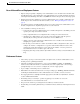
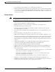
Cisco EtherSwitch Service Modules Feature Guide Information About the Cisco EtherSwitch Service Modules Figure 1 Discovery Through CDP Hops Command device VLAN 16 VLAN 62 Member device 8 Member device 10 Member device 9 Device 12 Device 11 candidate device Device 13 Edge of cluster Candidate devices Device 15 101321 Device 14 Discovery of Candidates and Members Through Non-CDP-Capable and Noncluster-Capable Devices If a cluster command switch is connected to a non-CDP-capable third-party hu
Cisco EtherSwitch Service Modules Feature Guide Information About the Cisco EtherSwitch Service Modules Discovery of Candidates and Members Through Different VLANs If the cluster command switch is a Cisco EtherSwitch service module, the cluster can have cluster member switches in different VLANs. As cluster member switches, they must be connected through at least one VLAN in common with the cluster command switch.
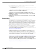
Cisco EtherSwitch Service Modules Feature Guide Information About the Cisco EtherSwitch Service Modules • Switch 9 because automatic discovery does not extend beyond a noncandidate device, which is switch 7 Figure 4 Discovery Through Different Management VLANs with a Layer 3 Cluster Command Switch Command device Standby command device VLAN 9 VLAN 16 VLAN 16 VLAN 62 Device 5 (management VLAN 62) VLAN trunk 4, 62 Device 7 (management VLAN 4) Device 4 (management VLAN 16) VLAN 62 Device 9 (managemen
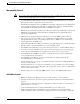
Cisco EtherSwitch Service Modules Feature Guide Information About the Cisco EtherSwitch Service Modules Figure 5 Discovery Through Routed Ports Command device VLAN 9 RP RP VLAN 62 VLAN 9 VLAN 62 VLAN 9 Member device 7 (management VLAN 62) 101324 VLAN 4 Discovery of Newly Installed Switches in Clusters To join a cluster, the new, out-of-the-box switch must be connected to the cluster through one of its access ports. An access port (AP) carries the traffic of and belongs to only one VLAN.
Cisco EtherSwitch Service Modules Feature Guide Information About the Cisco EtherSwitch Service Modules HSRP and Standby Cluster Command Switches The switch supports Hot Standby Router Protocol (HSRP) so that you can configure a group of standby cluster command switches.
Cisco EtherSwitch Service Modules Feature Guide Information About the Cisco EtherSwitch Service Modules Virtual IP Addresses in Clusters You need to assign a unique virtual IP address and group number and name to the cluster standby group. This information must be configured on a specific VLAN or routed port on the active cluster command switch. The active cluster command switch receives traffic destined for the virtual IP address.
Cisco EtherSwitch Service Modules Feature Guide Information About the Cisco EtherSwitch Service Modules • Each standby-group member (Figure 7) must be connected to the cluster command switch through the same VLAN. In this example, the cluster command switch and standby cluster command switches are Cisco EtherSwitch service module cluster command switches. Each standby-group member must also be redundantly connected to each other through at least one VLAN in common with the switch cluster.
Cisco EtherSwitch Service Modules Feature Guide Information About the Cisco EtherSwitch Service Modules • This limitation applies to all clusters: If the active cluster command switch fails and becomes active again, it does not discover any Catalyst 1900, Catalyst 2820, and Catalyst 2916M XL cluster member switches. You must again add these cluster member switches to the cluster.
Cisco EtherSwitch Service Modules Feature Guide Information About the Cisco EtherSwitch Service Modules Passwords in Clusters You do not need to assign passwords to an individual switch if it will be a cluster member. When a switch joins a cluster, it inherits the command-switch password and retains it when it leaves the cluster. If no command-switch password is configured, the cluster member switch inherits a null password. Cluster member switches only inherit the command-switch password.
Cisco EtherSwitch Service Modules Feature Guide Information About the Cisco EtherSwitch Service Modules Table 1 Basic Comparison of Switch Stacks and Switch Clusters (continued) Switch Stack Switch Cluster A switch stack can be a cluster command switch or a cluster member switch. A switch cluster cannot be a stack master or stack member.
Cisco EtherSwitch Service Modules Feature Guide How to Configure the Cisco EtherSwitch Service Module • If the cluster command switch is a switch stack and new stack masters are simultaneously elected in the cluster command switch stack and in cluster member switch stacks, connectivity between the switch stacks is lost if there are no redundant connections between the switch stack and the cluster command switch. You must add the switch stacks to the cluster, including the cluster command switch stack.
Cisco EtherSwitch Service Modules Feature Guide How to Configure the Cisco EtherSwitch Service Module • For device manager requirements, see the “System Requirements” section in the release notes (not orderable but available on Cisco.com). • For Network Assistant requirements, see Getting Started with Cisco Network Assistant (not orderable but available on Cisco.com).
Cisco EtherSwitch Service Modules Feature Guide How to Configure the Cisco EtherSwitch Service Module The interface numbering format on the Cisco EtherSwitch service module is stack-member-number/0/switch-port. For more detailed information about interface types, see the Catalyst 3750 Switch Software Configuration Guide, Cisco IOS Release 12.2 at the following URL: http://www.cisco.com/univercd/cc/td/doc/product/lan/cat3750/index.
Cisco EtherSwitch Service Modules Feature Guide How to Configure the Cisco EtherSwitch Service Module Configuring the Cisco EtherSwitch Service Module in the Router This section describes how to perform the initial configuration on the router with a Cisco EtherSwitch service module installed. This section also describes the initial configuration on the Cisco EtherSwitch service module itself.
Cisco EtherSwitch Service Modules Feature Guide How to Configure the Cisco EtherSwitch Service Module Step 3 Command or Action Purpose enable Enters privileged EXEC mode. Example: Router# enable Step 4 show running configuration Example: Displays the running configuration of the router, which should have a Gigabit Ethernet interface representing the Cisco EtherSwitch service module.
Cisco EtherSwitch Service Modules Feature Guide How to Configure the Cisco EtherSwitch Service Module Step 13 Command or Action Purpose enable Enters privileged EXEC mode on the Cisco EtherSwitch service module. Example: Switch> enable Step 14 show ip interface brief Displays brief version of the Cisco EtherSwitch service module configuration information.
Cisco EtherSwitch Service Modules Feature Guide How to Configure the Cisco EtherSwitch Service Module Examples This section provides the following examples: • Sample Output for the dir flash: Command on the Router, page 39 • Sample Output for the boot flash: Command on the Router, page 39 • Sample Output for the show running config Command on the Router, page 40 • Sample Output for Configuring the Cisco EtherSwitch Service Module Interface on the Router, page 40 • Sample Output for the service-mod
Cisco EtherSwitch Service Modules Feature Guide How to Configure the Cisco EtherSwitch Service Module Sample Output for the show running config Command on the Router The following example shows what appears when you enter the show running config command: Router# show running config interface gigabitethernet2/0 Building configuration...
Cisco EtherSwitch Service Modules Feature Guide How to Configure the Cisco EtherSwitch Service Module Sample Output for the show ip interface brief Command on the Cisco EtherSwitch Service Module The following example shows what appears when you enter the show ip interface brief command: Switch# show ip interface brief Interface IP-Address Vlan1 unassigned FastEthernet1/0/1 unassigned FastEthernet1/0/2 unassigned FastEthernet1/0/3 unassigned FastEthernet1/0/4 unassigned FastEthernet1/0/5 unassigned OK? Y
Cisco EtherSwitch Service Modules Feature Guide How to Configure the Cisco EtherSwitch Service Module Default Settings After Initial Cisco EtherSwitch Service Module Configuration The Cisco EtherSwitch service module is designed for plug-and-play operation. You need only assign basic IP information to the Gigabit Ethernet interface on the router representing the Cisco EtherSwitch service module and open a console session to Cisco EtherSwitch service module.
Cisco EtherSwitch Service Modules Feature Guide How to Configure the Cisco EtherSwitch Service Module Table 2 Default Settings (continued) Feature Default Setting Default VLAN VLAN 1 VLAN trunking Dynamic auto (DTP) Trunk encapsulation Negotiate 4 VTP mode Server VTP version 1 Voice VLAN Disabled STP 5 PVST+6 enabled on VLAN 1 MSTP7 Disabled Optional spanning-tree features Disabled DHCP snooping DHCP snooping Disabled DHCP snooping information option Enabled IGMP snooping IGMP
Cisco EtherSwitch Service Modules Feature Guide How to Configure the Cisco EtherSwitch Service Module 1. Only if the device acting as a DCHP server is configured and enabled. 2. Only if the device acting as a DHCP relay agent is configured and enabled. 3. DNS = Domain Name System 4. VTP = VLAN Trunking Protocol 5. STP = Spanning Tree Protocol 6. PVST+ = Per VLAN Spanning Tree Enhanced 7. MSTP = Multi-service Transport Platforms 8. IGMP = Internet Group Management Protocol 9.
Cisco EtherSwitch Service Modules Feature Guide How to Configure the Cisco EtherSwitch Service Module Note • Enable password • Telnet password If your Cisco EtherSwitch service modules are stacked and there are multiple console connections to individual Cisco EtherSwitch service modules in the stack, the initial setup dialog appears on the first console where the user presses Enter. SUMMARY STEPS 1. When prompted to enter the initial configuration dialog, enter yes. 2.
Cisco EtherSwitch Service Modules Feature Guide How to Configure the Cisco EtherSwitch Service Module Command or Action Purpose Step 4 Enter an enable password, and press Return. Sets the password to access privileged EXEC mode. Step 5 Enter a virtual terminal (Telnet) password, and press Return. Sets the Telnet password. Enter yes to configure SNMP. (Optional) Configures Simple Network Management Protocol (SNMP).
Cisco EtherSwitch Service Modules Feature Guide How to Configure the Cisco EtherSwitch Service Module Basic management setup configures only enough connectivity for management of the system, extended setup will ask you to configure each interface on the system.
Cisco EtherSwitch Service Modules Feature Guide How to Configure the Cisco EtherSwitch Service Module Sample Output for Saving the Configuration to NVRAM The following example shows what appears when you save the Cisco EtherSwitch service module configuration to NVRAM: [0] Go to the IOS command prompt without saving this config. [1] Return back to the setup without saving this config. [2] Save this configuration to nvram and exit.
Cisco EtherSwitch Service Modules Feature Guide How to Configure the Cisco EtherSwitch Service Module Step 2 Command or Action Purpose service-module gigabitethernet slot/unit reset Performs a hardware reset of the Cisco EtherSwitch service module. Example: Router# service-module gigabitethernet1/0 reset Step 3 service-module gigabitethernet slot/unit reload Performs a graceful halt and reload of the Cisco EtherSwitch service module operating system.
Cisco EtherSwitch Service Modules Feature Guide How to Configure the Cisco EtherSwitch Service Module in a Switch Stack How to Configure the Cisco EtherSwitch Service Module in a Switch Stack This section describes how to configure the Cisco EtherSwitch service module in a switch stack. A switch stack is a set of Cisco EtherSwitch service modules connected through their Cisco StackWise ports. One of the Cisco EtherSwitch service modules controls the operation of the stack and is called the stack master.
Cisco EtherSwitch Service Modules Feature Guide How to Configure the Cisco EtherSwitch Service Module in a Switch Stack Default Switch Stack Configuration Table 3 shows the default switch stack configuration.
Cisco EtherSwitch Service Modules Feature Guide How to Configure the Cisco EtherSwitch Service Module in a Switch Stack • Removing powered-up stack members from the stack causes the Cisco EtherSwitch service module stack to divide (partition) into two or more switch stacks, each with the same configuration. This can cause an IP address configuration conflict in your network. If you want the switch stacks to remain separate, change the IP address or addresses of the newly created switch stacks.
Cisco EtherSwitch Service Modules Feature Guide How to Configure the Cisco EtherSwitch Service Module in a Switch Stack Step 4 Command or Action Purpose reload slot stack-member-number Resets the stack member, and applies the configuration change. Example: Switch# reload slot 2 Step 5 Displays information about the switch stack and its stack members.
Cisco EtherSwitch Service Modules Feature Guide How to Configure the Cisco EtherSwitch Service Module in a Switch Stack Sample Output for the show switch Command The following example shows what appears when you enter the show switch command: Switch# Role Mac Address Priority State -------------------------------------------------------6 Slave 0003.e31a.1e00 1 Ready *8 Master 0003.e31a.1200 1 Ready 2 Slave 0000.000.
Cisco EtherSwitch Service Modules Feature Guide How to Configure the Cisco EtherSwitch Service Module in a Switch Stack Examples This section provides the following examples: • Sample Output for the switch priority Command, page 55 • Sample Output for the show switch Command, page 55 Sample Output for the switch priority Command The following example shows what appears when you enter the switch stack-member-number priority priority-number command: Switch(config)# switch 2 priority 15 Changing the Swit
Cisco EtherSwitch Service Modules Feature Guide How to Configure the Cisco EtherSwitch Service Module in a Switch Stack DETAILED STEPS Step 1 Use the show platform stack-manager command to display platform-dependent switch-stack information.
Cisco EtherSwitch Service Modules Feature Guide How to Configure a Switch Cluster Switch(config)# show switch neighbors Switch # Port A Port B -------- ------ -----6 None 8 8 6 None • Use the show switch stack-ports user EXEC command to display port status on the stack members: Switch(config)# Switch # Port A -------- -----6 Down 8 Ok show switch stack-ports Port B -----Ok Down How to Configure a Switch Cluster This section describes how to configure the Cisco EtherSwitch service module in a cluster.
Cisco EtherSwitch Service Modules Feature Guide How to Configure a Switch Cluster This section contains the following procedures: • Using the CLI to Manage Switch Clusters, page 58 • Adding Cluster Members to the Cisco EtherSwitch Service Module, page 60 • Creating a Cluster Standby Group, page 62 Using the CLI to Manage Switch Clusters This section shows how to use the CLI to manage switch clusters.
Cisco EtherSwitch Service Modules Feature Guide How to Configure a Switch Cluster Step 3 Command or Action Purpose exit Exits privileged EXEC mode on the cluster member service module to return to the command service module CLI. Example: Switch-3# exit Step 4 show cluster members Displays information about the cluster members.
Cisco EtherSwitch Service Modules Feature Guide How to Configure a Switch Cluster Adding Cluster Members to the Cisco EtherSwitch Service Module This section shows how to add cluster members to the Cisco EtherSwitch service module. The cluster command service module or switch automatically discovers candidate Cisco EtherSwitch service modules or switches.
Cisco EtherSwitch Service Modules Feature Guide How to Configure a Switch Cluster DETAILED STEPS FROM THE NETWORK ASSISTANT APPLICATION Command or Action Purpose Step 1 Close the Add to Cluster window. Closes the Add to Cluster window to view an updated list of cluster members. Step 2 Choose View > Refresh. Displays an updated list of cluster members. Step 3 Choose Cluster > Add to Cluster. Allows you to select a candidate service module from the cluster list.
Cisco EtherSwitch Service Modules Feature Guide How to Configure a Switch Cluster DETAILED STEPS FROM THE CLI Step 1 Command or Action Purpose cluster member Adds members to the cluster. • Example: Switch(config)# cluster member mac-address 00E0.1E00.3333 Step 2 The example shows how to add a switch with MAC address 00E0.1E00.3333 to the cluster. This switch does not have a password.
Cisco EtherSwitch Service Modules Feature Guide Upgrading the Cisco EtherSwitch Service Module Software Restrictions • This task is available only on the stack master. • You must enter a virtual IP address for the cluster standby group. This address must be in the same subnet as the IP addresses of the Cisco EtherSwitch service module. The group number must be unique within the IP subnet. It can be from 0 to 255, and the default is 0. The group name can have up to 31 characters. 1. enable 2.
Cisco EtherSwitch Service Modules Feature Guide Upgrading the Cisco EtherSwitch Service Module Software SUMMARY STEPS 1. enable 2. configure terminal 3. interface switch/slot/port 4. no switchport 5. ip address ip address/subnet mask 6. no shutdown 7. end 8. show flash 9. copy tftp: flash: DETAILED STEPS Step 1 Command or Action Purpose enable Enters privileged EXEC mode. Example: Switch> enable Step 2 configure terminal Enters global configuration mode.
Cisco EtherSwitch Service Modules Feature Guide Upgrading the Cisco EtherSwitch Service Module Software Step 8 Command or Action Purpose show run interface fastethernet switch/slot/port Shows the configuration applied on this interface. Example: Switch# show run interface fastEthernet 1/0/24 Step 9 Pings the TFTP server. This command copies an image from a TFTP server to flash memory.
Cisco EtherSwitch Service Modules Feature Guide Troubleshooting the Cisco EtherSwitch Service Module Software Sample Output for the show flash: Command The following example shows what appears when you enter the show flash: command: Switch# show flash: Directory of flash:/ 3 4 5 6 -rwx -rwx -rwx -rwx 4815232 6496 2377 5 Jan 1 May 11 Mar 1 Mar 1 1970 2004 1993 1993 00:10:53 10:43:15 04:33:45 04:33:46 +00:00 +00:00 +00:00 +00:00 c3825-i5-mz.050404 vlan.dat config.text private-config.
Cisco EtherSwitch Service Modules Feature Guide Troubleshooting the Cisco EtherSwitch Service Module Software Recovering from a Corrupted Software Image Using Xmodem This section describes how to recover from a corrupted software image by using Xmodem. Note The router should have the switch image in the router flash memory or have network connectivity to the TFTP server.
Cisco EtherSwitch Service Modules Feature Guide Troubleshooting the Cisco EtherSwitch Service Module Software 7. service-module interface slot/port session 8. dir flash: 9. boot flash: image DETAILED STEPS Step 1 Command or Action Purpose service-module interface slot/port password-reset Ensures that the switch stays at the boot loader prompt, so that you can copy a new image through the Xmodem Protocol.
Cisco EtherSwitch Service Modules Feature Guide Troubleshooting the Cisco EtherSwitch Service Module Software Step 8 Command or Action Purpose dir flash: Displays a list of all files and directories in flash memory on the service module. Example: switch> dir flash: Step 9 boot flash: image Example: Boots the Cisco EtherSwitch service module image if all files and directories are in flash memory on the service module. switch> boot flash:c3825-i5-mz.
Cisco EtherSwitch Service Modules Feature Guide Troubleshooting the Cisco EtherSwitch Service Module Software You are prompted for the service module interface number. Accept the default: Service Module interface number? [0]: You are prompted to confirm the buffer. Accept the default: 1k buffer? [confirm] You are prompted for the max retry count. Accept the default: Max Retry Count [10]: You are prompted to confirm the transfer to the Cisco EtherSwitch service module: Xmodem send on slot 2 interface 0.
Cisco EtherSwitch Service Modules Feature Guide Troubleshooting the Cisco EtherSwitch Service Module Software You are prompted for the max retry count. Accept the default: Max Retry Count [10]: You are prompted to confirm the transfer to the Cisco EtherSwitch service module: Xmodem send on slot 2 interface 0. Please be sure there is enough space on receiving side. Continue? [confirm] The following appears when the image is downloaded to the service module: Ready to send file...........
Cisco EtherSwitch Service Modules Feature Guide Troubleshooting the Cisco EtherSwitch Service Module Software the flash filesystem, and finish loading the operating system software: flash_init load_helper boot Router: Sample Output for the flash_init Command on the Cisco EtherSwitch Service Module The following example shows what appears when you enter the flash_init command: Switch: flash_init Initializing Flash...
Cisco EtherSwitch Service Modules Feature Guide Troubleshooting the Cisco EtherSwitch Service Module Software SUMMARY STEPS 1. service-module interface slot/port session 2. dir flash: 3. service-module interface slot/port password-reset 4. flash_init 5. (Optional) load_helper filesystem:/file-url ... 6. rename 7. boot 8. copy flash: 9. configure terminal 10. enable secret password 11. exit 12. copy running-configuration startup-configuration 13.
Cisco EtherSwitch Service Modules Feature Guide Troubleshooting the Cisco EtherSwitch Service Module Software Step 6 Command or Action Purpose rename Renames the configuration file to config.text.old. • Example: Switch: rename flash:config.text flash:config.text.old Step 7 boot [-x] [-v] [device:][imagename] Before continuing to the next command, power up any connected stack members and wait until they have completely initialized. Use the boot command to boot up an external process.
Cisco EtherSwitch Service Modules Feature Guide Troubleshooting the Cisco EtherSwitch Service Module Software Step 12 Command or Action Purpose copy running-configuration startup-configuration Copies the configuration from the running configuration file to the switch startup configuration file. Example: Switch: copy running-config startup-config Step 13 reload • This procedure is likely to leave your Cisco EtherSwitch service module virtual interface in a shut down state.
Cisco EtherSwitch Service Modules Feature Guide Troubleshooting the Cisco EtherSwitch Service Module Software Recovering from a Lost or Forgotten Password When Password Recovery Is Disabled This section shows how to recover from a lost or forgotten password when password recovery is disabled. When password recovery is disabled, access to the boot loader prompt through the password-recovery mechanism is disallowed even though the password-recovery mechanism has been triggered.
Cisco EtherSwitch Service Modules Feature Guide Troubleshooting the Cisco EtherSwitch Service Module Software DETAILED STEPS Step 1 Command or Action Purpose service-module interface slot/port password-reset Resets the password on the router. Example: Router# service-module gigabitethernet1/0 password-reset Step 2 service-module interface slot/port session Example: Connects to the service module and opens a service module session.
Cisco EtherSwitch Service Modules Feature Guide Switch Stack Configuration Scenarios Step 9 Command or Action Purpose exit Returns you to privileged EXEC mode. Example: Switch(config): exit Step 10 copy running-configuration startup-configuration Example: Switch: copy running-config startup-config Step 11 Copies the configuration from the running configuration file to the switch startup configuration file.
Cisco EtherSwitch Service Modules Feature Guide Switch Stack Configuration Scenarios Table 4 Switch Stack Configuration Scenarios Scenario Action Stack master election Connect two powered-up switch stacks specifically determined through the Cisco StackWise ports.
Cisco EtherSwitch Service Modules Feature Guide Switch Stack Configuration Scenarios Table 4 Switch Stack Configuration Scenarios (continued) Scenario Action Result Stack master election specifically determined by the cryptographic IP base image Assuming that all stack members have the same priority value: The stack member with the cryptographic IP base image is elected stack master. 1.
Cisco EtherSwitch Service Modules Feature Guide Network Configuration Examples Table 4 Switch Stack Configuration Scenarios (continued) Scenario Action Result Stack master failure Remove (or power down) the stack master. Based on the factors described in the “Stack Master Election and Re-Election” section on page 14, one of the remaining stack members becomes the new stack master. All other stack members in the stack remain as stack members and do not reboot. 1.
Cisco EtherSwitch Service Modules Feature Guide Network Configuration Examples Table 5 Increasing Network Performance Network Demands Suggested Design Methods Too many users on a single network segment and a growing number of users accessing the Internet • Increased power of new PCs, workstations, and servers • High bandwidth demand from networked applications (such as e-mail with large attached files) and from bandwidth-intensive applications (such as multimedia) • Create smaller network segment
Cisco EtherSwitch Service Modules Feature Guide Network Configuration Examples Providing Network Services (continued) Network Demands Suggested Design Methods High demand on network redundancy and availability to provide always on mission-critical applications An evolving demand for IP telephony • Use switch stacks, where all stack members are eligible stack masters in case of stack master failure.
Cisco EtherSwitch Service Modules Feature Guide Network Configuration Examples • Redundant gigabit backbone (Figure 9)—Using HSRP, you can create backup paths between two Cisco EtherSwitch service modules to enhance network reliability and load balancing for different VLANs and subnets. Using HSRP also provides faster network convergence if any network failure occurs. You can connect the Catalyst switches, again in a star configuration, to two Cisco EtherSwitch service modules.
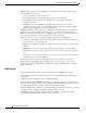
Cisco EtherSwitch Service Modules Feature Guide Network Configuration Examples Figure 10 High-Performance Wiring Closet Internet Cisco integrated services router with EtherSwitch service module Catalyst 3750 multilayer StackWise switch stack IP Cisco IP phones IP Workstations running Cisco SoftPhone software Aironet wireless access points 121821 Gigabit servers Multidwelling Network Using the Cisco EtherSwitch Service Modules A growing segment of residential and commercial customers is requiring
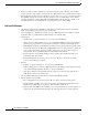
Cisco EtherSwitch Service Modules Feature Guide Network Configuration Examples Figure 11 Cisco EtherSwitch Service Modules in a MAN Configuration Cisco 12000 Gigabit switch routers Catalyst 6500 switches Service Provider POP Si Si Mini-POP Gigabit MAN Cisco integrated services router with EtherSwitch service module Si Cisco integrated services router with EtherSwitch service module Catalyst 3750 StackWise switch stack Residential location Catalyst switches Set-top box Residential gateway (hub)
Cisco EtherSwitch Service Modules Feature Guide Additional References Additional References Related Documents Related Topic Document Title Hardware installation instructions for network modules Cisco Interface Cards Installation Guide General information about voice configuration and command reference.
Cisco EtherSwitch Service Modules Feature Guide Additional References Cisco IOS Release 12.