GETTING STARTED GUIDE Linksys Business Series Network Storage System Getting Started Guide Linksys Business Series Network Storage System Models NSS4000 and NSS6000 Series
© 2007-2008 Copyright 2007-2008, Cisco Systems, Inc. Specifications are subject to change without notice. Linksys, the Cisco Systems logo, the Linksys Logo, and the Linksys One logo are registered trademarks of Cisco Systems, Inc. All other trademarks mentioned in this document are the property of their respective owners.
Contents Linksys Business Series Network Storage System Administrator Guide Contents Chapter 1: Introduction . . . . . . . . . . . . . . . . . . 3 Benefits About this Guide... Recommended Installation Sequence 3 3 4 Chapter 2: Part A: Set up the Hardware . . . . . . . . . . . .
Contents Linksys Business Series Network Storage System Administrator Guide Mac Users: Accessing Storage through CIFS/SMB Mac Users: Accessing Storage through FTP 47 48 Chapter 5: LEDs & Buttons . . . . . . . . . . . . . . . . .
Chapter Getting Started Guide Introduction Thank you for choosing the Linksys Business Series Network Storage System (NSS). Administering a network can be a difficult job. Finding low-cost ways to simplify your datamanagement tasks means that you have more resources to dedicate elsewhere. The NSS is a Network Attached Storage (NAS) unit that appears as a native file server for the various clients within your network, including Windows, Apple Macintosh, UNIX, and Linux platforms.
Chapter 1 Getting Sarted Guide Recommended Installation Sequence Follow the NSS installation steps to set up and configure the device. They provide out-of-the-box instructions. You can find detailed instructions for each step in the remaining sections of this guide. • Part A: Set up the hardware: - Step 1: Install the disk drives. Skip this step if you have an NSS4100 or NSS6100 as they are already equipped with disk drives. - Step 2: Connect the Ethernet cable(s). - Step 3: Connect the power.
Chapter Getting Started Guide - Step 13: Go through the rest of the configuration options to set up quotas, edit groups, set up email and SNMP alerts, and so on. For more detailed information, refer to the Online Help from the Configuration Manager, or the Linksys Business Series Network Storage System Administrator Guide available from the Linksys website at www.linksys.com - Step 14: After you configure the NSS, save a copy of the configuration file to a location on the NSS and to a USB key.
Chapter 1 Getting Sarted Guide 6 Chapter 1: Introduction Recommended Installation Sequence
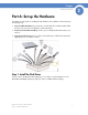
Chapter Getting Started Guide Part A: Set up the Hardware This chapter provides details for installing the NSS hardware. The installation is broken down into the following steps: 1. Step 1: Install the Disk Drives: If your NSS does not have disk drives already installed, follow the steps in this section to insert disk drives into the NSS chassis. 2. Step 2: Connect the Ethernet Cable(s): Connect up to two Ethernet links from the NSS to your network. 3.
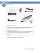
Chapter 2 Getting Sarted Guide To install the disk drives into the NSS: 1. Remove a disk tray from the front of the NSS chassis by pushing in the tab on the front of the tray. (There is no recommended order of which tray to remove first.) The disk drives are numbered from 1 to 4 (left to right) in the front of the chassis. 2. Position the disk drive into a disk tray. 3.
Chapter Getting Started Guide 7. If the NSS is rack mounted, attach the mounting ears to both sides of the NSS. Attach the mounting ears to either side of the rack. 8. Continue with Step 2 to install the Ethernet cable(s). Approved Vendor List for Drives If you are purchasing disk drives to install in the NSS, refer to the product support information offered on the Linksys website (www.linksys.com) for a list of recommended disk drives.
Chapter 2 Getting Sarted Guide NOTE: If you are hotplugging an Ethernet cable to the NSS after the initial installation, ensure you wait 15 seconds between the time you unplug the cable and plug it back in. Within 10 seconds the newly connected link should appear with the correct IP and link rate in the configuration interface. To connect the Ethernet cable(s) to the NSS: 1. Install the Ethernet cable to the Ethernet port at the back of the NSS chassis.
Chapter Getting Started Guide NSS-supported UPS Product Families The NSS supports the following UPS product families: • APC Back-UPS Pro USB • APC Back-UPS RS USB • APC Back-UPS USB • APC Back-UPS LS USB • APC Back-UPS ES/CyberFort 350 • APC Smart-UPS USB Chapter 2: Setting up the Hardware Step 3: Install the Power 11 2
Chapter 2 Getting Sarted Guide 12 Chapter 2: Setting up the Hardware Step 3: Install the Power
Chapter Getting Started Guide Part B: Configure the Network Storage System (NSS) There are a variety of ways to configure the NSS, depending on your specific storage needs and your unique networking environment. This section covers the steps you need to follow to get the NSS configured so that you can start using its storage.
Chapter 3 Getting Sarted Guide • Step 9 – Add any Locally Defined Users and Groups: You can create and maintain a list of users and groups from the NSS. • Step 10 – Create Shares: After you create a volume, you can create the shares and set up access privileges to those shares for the users and groups. You can also define the DFS access. • Step 11 – Create the Volume Snapshots: If you have an NSS6000 series unit, you can configure snapshots for each volume.
Chapter Getting Started Guide To set up your computer to communicate with the NSS: 1. Set your computer’s network settings to the following: • IP Address: 169.254.x.y (where x and y can be any number between 1 and 254). For example, 169.254.1.2. • Subnet Mast (Netmask): 255.255.0.0. After you configure your computer, you can log into the NSS configuration interface. You can configure the NSS network IP settings as required.
Chapter 3 Getting Sarted Guide A new tab appears with the hostname of the NSS. 4. Click the NSS tab. The NSS device is automatically assigned an IP address from the DHCP server in the SVR series router. The NSS device configuration interface appears, with the System Status page open: 5. It is a good idea to do a quick check of the information on the System Status page to ensure that your hardware installation was successful and that this system is not reporting any errors.
Chapter Getting Started Guide Option B: Standalone Environment Login Steps To log into the configuration interface: 1. If you are logging into the NSS for the first time, write down the MAC address located on the sticker attached to the bottom of the chassis. You need the MAC address as this is part of the default hostname. Otherwise, skip this step. 2. There are a variety of ways to display the NSS Login window.
Chapter 3 Getting Sarted Guide The NSS configuration interface appears, with the System Status page open: 5. It is a good idea to do a quick check of the information on the System Status page to ensure that your hardware installation was successful and that this system is not reporting any errors. For example, the Ethernet link(s) are up and in good condition, the right number of disk drives installed appear, and so on.
Chapter Getting Started Guide To configure the time settings for the NSS: 1. From the Manager Menu, click Admin Time. The NTP Configuration page appears. 2. To use an NTP server to maintain the NSS time, click Automatically (via NTP). To assign the time manually, skip to step 4. 3. If your DHCP server is configured to provide NTP settings, select “Assign automatically via DHCP”. If not, manually configure the NTP settings.
Chapter 3 Getting Sarted Guide NOTE: When adding disks to an array, we recommend you use the same model of disk with the same capacity. With the exception of a JBOD, RAIDs are configured to use the maximum of the smallest disk capacity in the array for each additional disk in the array. For example, if you install two, 250 GB disks and one 500 GB disk in a RAID0 array, the total capacity is only 750 GB. It takes approximately 1.6GB/min (NSS4000) and 2.6GB/min (NSS6000) to build a RAID5 array.
Chapter Getting Started Guide 3. From the RAID Level drop-down menu, click the RAID level of the RAID array you want to create. 4. Click Add. The RAID creation can take some time to complete (depending on the size of the disks and the selected RAID level). You can monitor the progress of the RAID build from the Storage Status page. When the build is finished, the array appears in the RAID Arrays table. The disks used in the array are no longer available for creating additional arrays.
Chapter 3 Getting Sarted Guide • Size: Enter the size for the volume, and then select the unit from the drop-down menu. The final size of the shared volume is less than the size you enter in this field due to filesystem overhead. The minimum volume size is 32 MB. Volume sizes are rounded down to the nearest 32 MB increment. NOTE: Once the volume is created, you can expand the volume but you cannot reduce its size. • To encrypt the volume, select Encrypted. To create an unencrypted volume, go to step 6.
Chapter Getting Started Guide Step 6: Virtualize Storage within your Network The NSS virtualization feature lets you create storage physically located on other network NSS units into one logical storage unit. The recommended network configuration for using virtualization is to use an NSS6000 series to operate as the “master” storage device (the “slave” devices can either be NSS6000 series, NSS4000 series, or NSS2000 series devices).
Chapter 3 Getting Sarted Guide The Storage Virtualization page appears. 3. From the Export a device area, select each device that you want to export from the list of available devices. 4. From the Link field, select the physical link that you want to use to export the storage. 5. Click Export. The selected disk(s) disappear from the available list of arrays and appear in the Currently Exported Storage table at the top of the page.
Chapter Getting Started Guide The RAID page appears. Exported disks from other NSS units in the network appear in the New RAID Device table. 3. From the New RAID Device table, click the disks or arrays that you want to include in the JBOD. 4. Select JBOD as the RAID level. 5. Click Add. The JBOD appears in the RAID Arrays listing. You can now create volumes from the virtualized JBOD. Step 7: Configure the NSS Network Identification To configure the NSS network identity: 1.
Chapter 3 Getting Sarted Guide The Network Identification page appears. 2. In the Hostname field, enter the name you want to use for the NSS. Note any special naming restrictions or conventions enforced by the domain(s) into which the NSS is being joined. Caution: If you change the hostname, any current CIFS connections to shares on the NSS are disconnected. 3. To assign the hostname for the NSS using the DHCP server, select Assign automatically via DHCP.
Chapter Getting Started Guide 5. Select the type of network into which you are making the NSS a member from the following options: • Workgroup: Make the NSS part of a peer-to-peer network. • NTv4 Domain: Make the NSS a part of a pre-Windows 2000 domain. If you select this option, set up the following fields: - NTv4 Domain: Enter the domain name. - Domain Controller: Enter the hostname or IP address of the domain controller.
Chapter 3 Getting Sarted Guide Step 8: Configure the User/Group Ranges and Home Directory Location To avoid conflicts between your user and group IDs, it is important to set up the ranges for the various types of users and groups (i.e., local, NIS domain, and Windows domain). The ID range should be set up before you create any local users or join a NIS, NTv4, or ADS domain as you should not change the range after the domain has been joined.
Chapter Getting Started Guide Step 9: Create any Locally Defined Users and Groups You can create, view, and maintain the list of users who can access the NSS. The Configured Users page displays the Configured Users table. This table lists each defined user whether the user was created locally via the NSS configuration interface or imported from an NTv4, Active Directory, or NIS domain. Note that users not created locally via the NSS are read-only.
Chapter 3 Getting Sarted Guide The New User page appears. 3. In the Username field, type the username. The name must be made up of alphanumeric characters (that is, a-z, 0-9), any case, to a maximum of 32 characters. This field is required. 4. Select the group you want to assign as the user’s primary group from the Primary Group field. If there are no groups configured, the only available choice is the default group “nasusers”. This field is required.
Chapter Getting Started Guide 7. To record the user’s email address, enter it in the Email Address field. This field is optional. 8. Click OK to create the user and exit the New User page. Click Apply to create the user and then add another new user. Creating a Group Groups let you specify the share access privileges for a set of users. After you create a group, you can define the group’s access privileges on a per-share basis. You can add or remove users to and from the group at any time.
Chapter 3 Getting Sarted Guide The New Group page appears. 3. In the Group Name field, type the name you want to assign to the group. The name can only contain lower-case alphanumeric characters and underscores (i.e., a-z, 0-9, _) to a maximum of 32 characters. 4. Move the users you want to assign to the group from the Users Available list to the Users in Group list. Note that a user can be assigned to multiple groups.
Chapter Getting Started Guide The New Share page appears. 3. In the Share field, enter a name for the share. 4. From the Location field, select the volume on which you want to configure the share. 5. Add a description or comment about the share in the Comment field. This comment appears when you browse the NSS from My Network Places (as the tooltip when you hover over the share, or if you select the Details viewing mode). This field is optional. 6.
Chapter 3 Getting Sarted Guide • DFS Root: Set the share to be a Microsoft DFS root. NOTE: The share must be set as a DFS root when it is created. You cannot set it as a DFS root after it is created or revert a DFS root share to be a regular share. When you set this option, the CIFS Default File Creation Attributes and Protocol checkboxes are greyed out as they are not relevant.
Chapter Getting Started Guide • Everyone Readable: All authenticated users can view the file. • Everyone Writable: All authenticated users have write permission to the file. 9. From the Protocol field, click the checkboxes to select the protocols that can be used to access the share: • CIFS: Enable CIFS access to the share. • NFS: Enable NFS access to the share. (Note: To allow NFS access to the share, the NSS must also be configured to allow NFS access.) • FTP: Enable FTP access to the share.
Chapter 3 Getting Sarted Guide The File Shares page appears. 2. Click Edit for the share to which you want to add a folder. The Edit Share page appears. 3. Click Add Shared Folder.
Chapter Getting Started Guide The Add Folder page appears. 4. Select one of the following: • Add a Folder to DFS: Select this option to create a single DFS shared folder. Fill in the following fields from the Add DFS Shared Folder table: - Link Name: This is the name of the link that appears as a folder within the share. When users click this link, they are redirected to the target share on the remote server. Enter any name of up to 255 characters.
Chapter 3 Getting Sarted Guide Restrictions using Microsoft DFS from the NSS To use DFS folders from the NSS, it is important to understand the limitations or restrictions involved and how to best configure your system: • User Credentials must be Recognized by the Remote Server: Re-direction to a remote fileserver is only successful if the current user credentials (i.e., the user’s NSS username and password) are recognized by the remote server.
Chapter Getting Started Guide snapshots is greater, the amount of the reserve should be greater. Or, if there is a heavy amount of activity on the volume, set a higher reserve. NOTE: This feature is only available on NSS6000 series NAS units. To create a snapshot for a volume: 1. From the Manager Menu, click Storage Snapshots. The Storage Snapshots page appears. 2. From the New Snapshot table, click the volume for which you are creating the snapshot. 3.
Chapter 3 Getting Sarted Guide 5. In the Reserve Size field, enter the amount of space that you want to allocate to the snapshot, and then select the unit from the drop-down menu. This space becomes unavailable for any other storage on the array. Note that you must enter a minimum of 32 MB in this field. NOTE: The snapshot is built at the array level. The Volume column currently shows the amount of space left on the array on which the volume is located.
Chapter Getting Started Guide The Scheduled Backups page appears. 3. Move the shares you want to include in the backup from the Available Shares list to the Shares to Backup list. (The single angled bracket “<“ or “>” moves the selection in the direction of the bracket. The double angled bracket “<<“ or “>>” moves the entire list in the direction of the bracket.) 4.
Chapter 3 Getting Sarted Guide The Select Backup Schedule page appears. 7. Select the backup frequency as one of the following: • Daily: Select each day on which you want the backup to occur. • Weekly: Select the day of the week on which you want the backup to occur. • Monthly: Select the day of the month on which you want the backup to occur. Make sure you select a day that is 28 or less. If you select the 29th, 30th or 31st day, the backup does not run during months that do not contain that day. 8.
Chapter Getting Started Guide Step 14: Save the Current Configuration You can save a copy of the NSS configuration that can be used should you need to restore the settings at a later time. When you save the configuration file, it saves a date-stamped version of the current configuration settings to the specified volume on the NSS. You can choose to save the current configuration settings to a specified volume on the NSS or you can save the file to a USB flash device inserted into the AUX-1 port.
Chapter 3 Getting Sarted Guide 6. If you saved the file to the USB flash device, display the Storage Status page. 7. Click Unmount. NOTE: Removing the USB flash device in a mounted state means that you risk causing file or filesystem corruption. 8. When the AUX-1 LED on the front of the chassis is off, you can safely remove the unmounted USB flash device from the AUX-1 port.
Chapter Getting Started Guide Part C: Instruct Your Users How to Access the NSS Storage End users, using a Windows, UNIX, Linux, or Mac computer can easily access NSS storage. Once the end user logs into the NSS using their username and password, the shares to which the end user has read or read-write privileges appear. The NSS supports three file-sharing protocols: CIFS, NFS, and FTP.
Chapter 4 Getting Sarted Guide Windows Users: Accessing the NSS Storage through FTP Windows users who have a user profile set up can access any shares to which they have privileges on the NSS storage using CIFS/SMB or FTP. NOTE: Before your end users can access the shares on the NSS using FTP, the NSS must have FTP access enabled and the individual share must be set up to allow FTP access. To access the NSS storage using FTP: 1. From your FTP client application, connect to the NSS.
Chapter Getting Started Guide UNIX/Linux Users: Accessing Storage through FTP UNIX and Linux users who have a user profile set up can access any shares to which they have privileges on the NSS storage using NFS or FTP. NOTE: Before your end users can access the shares on the NSS using FTP, the NSS network filters must be set up to allow FTP access. The individual share must be also be set up to allow FTP access. To access the NSS storage using FTP: 1. Open your FTP client application. 2.
Chapter 4 Getting Sarted Guide Mac Users: Accessing Storage through FTP Mac users who have a user profile can access any shares to which they have privileges on the NSS storage using FTP. NOTE: Before your end users can access the shares on the NSS using FTP, the NSS must have FTP access enabled and the individual share must be set up to allow FTP access. To access the NSS storage using FTP: 1. Open your FTP client application. 2. Click Connect. 3. From your FTP client application, connect to the NSS.
Chapter Getting Started Guide LEDs & Buttons The LEDs on the front and back of the NSS chassis help you troubleshoot a variety of conditions on the NSS---from normal operating conditions, alerts, to serious error conditions. The Reset button lets you restore the network defaults in situations where you can no longer log into the configuration interface.
Chapter 5 Getting Sarted Guide System LED (Front Panel) The System LED can be in any of the following conditions, depending on the current type of system error on the NSS: • Solid Yellow: The administrator needs to look into the exact error condition through the configuration interface as one of the following has occurred: - A volume is more than 90% full. - A disk drive has failed or is about to fail. - A fan has stalled. - The system temperature is above the maximum threshold.
Chapter Getting Started Guide LAN LEDs (Front Panel) Solid Green: The LAN link is up and running at 1000 link speed, but is currently idle. Blinking Green: The LAN link is up and running at 1000 link speed and is currently active. The LED flickers off with activity. Solid Yellow: The LAN link is up and running at 10/100 link speed, but is currently idle. Blinking Yellow: The LAN link is up and running at 10/100 link speed and is currently active. The LED flickers off with activity.
Chapter 5 Getting Sarted Guide USB LED (Front Panel) Solid Green: The USB hard/flash drive is connected and is not safe to remove. Blinking Green: The USB hard/flash drive is connected and is being mounted or unmounted. Off: There is either no USB hard/flash drive connected to the NSS, or, if connected, the USB hard/flash drive is safe to remove.
Appendix Network Storage System (NSS) Getting Started Guide Support Contact Information Linksys One Contact Information Visit Linksys online for information on the latest products and product updates at: http://www.linksys.