ALPHA DRAFT - CISCO CONFIDENTIAL Text Part Number: 78-6030-01 Cisco uBR7200 Series Universal Broadband Router Wireless Modem Card and Subsystem Installation and Configuration Product Numbers: UBR-MCW-PDA, UBR-MCW-PDA=, UBR-WPFD, UBR-WPFD=, UBR-ODU-PAA, UR-ODU-PAA=, UBR-ODD-01A, UBR-ODD-01A=, UBR-ODD-02A, UBR-ODD-02A=, UBR-ODD-03A, UBR-ODD-03A= This document explains how to install and configure the components for a high-speed point-to-point fixed broadband wireless system using Cisco uBR7200 series univer
ALPHA DRAFT - CISCO CONFIDENTIAL If You Need More Information • Cisco Connection Online, page 88 If You Need More Information The Cisco IOS software running on your router contains extensive features and functionality. The effective use of many of these features is easier if you have more information.
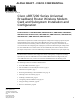
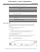
ALPHA DRAFT - CISCO CONFIDENTIAL Wireless Modem Card and Subsystem Overview The wireless modem cards are installed in a Cisco uBR7200 series router. Each modem card is cabled to a power feed panel installed either in the same equipment rack as the router or mounted on the wall. Cables from the power feed panel are connected to the outdoor unit which is installed either on the antenna pole or on a wall in close proximity to the antenna. The system is managed via a command line interface (CLI) or CiscoWorks.
ALPHA DRAFT - CISCO CONFIDENTIAL Wireless Modem Card and Subsystem Overview Wireless Modem Card The wireless modem card provides the control and data interface to the system’s digital motherboard and the radio frequency (RF) subsystem in the ODU. It also provides the up/down conversion from baseband to intermediate frequency (IF). Wireless modem cards consist of the following components: • • • • Main and diversity serial interface control connectors. 10 MHz external reference clock connection.
ALPHA DRAFT - CISCO CONFIDENTIAL Power Feed Panel Table 1 Wireless Modem Card Connectors (continued) Connector Type Function Diversity - PFP SMA (female) 48 MHz reference, receive and transmit IF signals (when diversity option is used). Main - Monitor SMA (female) For connection to spectrum analyzer for test/troubleshooting purposes. Main - PFP SMA (female) 48 MHz reference, receive and transmit IF signals.
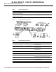
ALPHA DRAFT - CISCO CONFIDENTIAL Wireless Modem Card and Subsystem Overview Table 3 Power Feed Panel LEDs LED Function Main Power On (visible on front and rear panel) When lit, indicates that there is power going to the main ODU. Diversity Power On (visible on front and rear panel) When lit, indicates that there is power going to the diversity ODU.
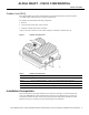
ALPHA DRAFT - CISCO CONFIDENTIAL Outdoor Unit (ODU) Outdoor Unit (ODU) The ruggedized ODU is the control and data interface to the indoor subsystems. It provides up/down conversion from IF to RF frequencies and power amplification. The outdoor unit consists of the following components: • • • RF head Connector ports for IF input, control, and test Duplexor assembly with antenna connection Figure 7 shows the connectors on the outdoor subsystem, and Table 5 describes their use.
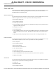
ALPHA DRAFT - CISCO CONFIDENTIAL Installation Prerequisites Parts and Tools The following sections describe the parts and tools required to install each of the components. If you need more detailed information regarding cables or connectors, refer to the Cisco Wireless Broadband Router Site Planning Guide. Wireless Modem Card You need the following tools and parts to remove and replace a wireless modem card. If you need additional equipment, contact a service representative for ordering information.
ALPHA DRAFT - CISCO CONFIDENTIAL Software and Hardware Requirements • • • Mounting kit (provided) Cable with N-type (male) connectors to cable the ODU to the antenna Mini-phone with 3.5 mm mono phone plug to use for antenna alignment tasks Software and Hardware Requirements The following hardware is required: • Configured Cisco uBR7200 series router The following software is required: • The Cisco uBR7200 series router must be running Cisco IOS Release 12.0(6)XA or later.
ALPHA DRAFT - CISCO CONFIDENTIAL Installation Prerequisites Warnhinweise finden Sie im Dokument Regulatory Compliance and Safety Information (Informationen zu behördlichen Vorschriften und Sicherheit), das zusammen mit diesem Gerät geliefert wurde. Avvertenza Questo simbolo di avvertenza indica un pericolo. La situazione potrebbe causare infortuni alle persone.
ALPHA DRAFT - CISCO CONFIDENTIAL Safety Guidelines Telephone Wiring Guidelines Use the following guidelines when working with any equipment that is connected to telephone wiring or to other network cabling: • • Never install telephone wiring during a lightning storm. • Never touch uninsulated telephone wires or terminals unless the telephone line has been disconnected at the network interface. • Use caution when installing or modifying telephone lines.
ALPHA DRAFT - CISCO CONFIDENTIAL Removing and Installing a Wireless Modem Card Following are guidelines for preventing ESD damage: • Always use an ESD wrist strap or ankle strap when installing or replacing the network processing engine, I/O controller, port adapters, or modem cards. Ensure that the ESD strap makes contact with your skin.
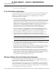
ALPHA DRAFT - CISCO CONFIDENTIAL Installing or Replacing a Wireless Modem Card Figure 9 Captive Installation Screws Step 3 Grasp the handle on the wireless modem card and carefully pull the modem card from the midplane, about halfway out of its slot. If you are removing a blank modem card, pull the blank modem card all the way out of the chassis slot. Step 4 With the wireless modem card halfway out of the slot, disconnect all cables from the front of the modem card.
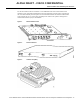
ALPHA DRAFT - CISCO CONFIDENTIAL Removing and Installing a Wireless Modem Card Figure 10 Aligning the Wireless Modem Card Metal Carrier Between the Slot Guides (Cisco uBR7246 Shown) 14 Cisco uBR7200 Series Universal Broadband Router Wireless Modem Card and Subsystem Installation and Configuration
ALPHA DRAFT - CISCO CONFIDENTIAL Installing or Replacing a Wireless Modem Card Figure 11 Step 4 Aligning the Wireless Modem Card Metal Carrier Between the Slot Guides (Cisco uBR7223 Shown) With the metal carrier aligned in the slot guides, gently slide the modem card halfway into the modem card slot. Caution Do not slide the modem card all the way into the slot until you have connected all required cables. Trying to do so will disrupt normal operation of the router.
ALPHA DRAFT - CISCO CONFIDENTIAL Installing a Power Feed Panel Cabling a Wireless Modem Card Attaching the RF Control Cables Insert the RJ45 connector on the control cable into the Main Control connector port. If you will be using the diversity option, use a second cable and attach it to the Diversity Control connector port. Attaching the IF and Monitor Cables Connect one end of the IF signal cable to the Main PFP port.
ALPHA DRAFT - CISCO CONFIDENTIAL Rack-Mounting a Power Feed Panel To install a power feed panel with the rear panel facing forward, attach the brackets to both sides of the unit as shown in Figure 13. Figure 13 Bracket Installation - Rear Panel Forward To install a power feed panel in a center-mount telco rack, attach the brackets to both sides of the unit as shown in Figure 14.
ALPHA DRAFT - CISCO CONFIDENTIAL Installing a Power Feed Panel Figure 16 Step 2 Attaching the Wall Mount Brackets Attach the power feed panel to the wall as shown in Figure 17, using (customer provided) screws and anchors. To best support the power feed panel and cables, attach the brackets so that the screws align with a vertical wall stud. (SeeFigure 17.) This position will prevent the unit from pulling away from the wall when the cables are attached.
ALPHA DRAFT - CISCO CONFIDENTIAL Wiring the DC Power Wiring the DC Power Follow the procedures in this section to wire the DC power. Note The color coding of DC-input power supply leads depends on the color coding of the DC power source at your site. Typically, green or green/yellow is used for ground, black is used for +48V (return), and red or white is used for –48V. Make certain the lead color coding you choose for the DC-input power supply matches lead color coding at the DC power source.
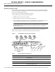
ALPHA DRAFT - CISCO CONFIDENTIAL Installing a Power Feed Panel Step 3 Using a wire stripper, strip approximately 0.55 in. (14 mm) from the +48V, –48V and ground leads. Step 4 Insert the stripped ends of the wire in the removable wiring block according to the scheme in Figure 19. Figure 19 illustrates the polarity of each connection. The connection on the left is for the –48VDC wire, the middle connection is for safety ground. The connection on the right is for the positive return wire.
ALPHA DRAFT - CISCO CONFIDENTIAL Cabling the Power Feed Panel Cabling the Power Feed Panel Connecting the Control Cables (from the Modem Card) Attach the end of the control cable coming from the Control-Main port on the modem card to the Control-Main/MC port on the power feed panel. If you will be using the diversity option, also attach the second control cable coming from the Control-Diversity port on the modem card to the Control-Diversity/MC port on the power feed panel.
ALPHA DRAFT - CISCO CONFIDENTIAL Installing an Outdoor Unit Determining the Orientation of the Duplexor The orientation of the duplexor when installed in the ODU, will determine its function. Figure 22 Duplexor Orientation Installing the Duplexor in the ODU Figure 23 Installing the Duplexor Mounting the Outdoor Unit The ODU can be mounted either on the antenna pole or on a wall depending on site requirements. A mounting kit is included for this purpose.
ALPHA DRAFT - CISCO CONFIDENTIAL Mounting the Outdoor Unit [CAUTIONS] Step 1 Figure 24 Attaching the Mounting Bracket to the Antenna Pole Step 2 Step 3 Figure 25 Attaching the ODU to the Mounting Bracket Step 4 Step 5 Mounting the Outdoor Unit on a Wall Use the following steps to mount the outdoor unit on a wall: [CAUTIONS] Step 1 Figure 26 Attaching the Mounting Bracket to the Wall Step 2 Cisco uBR7200 Series Universal Broadband Router Wireless Modem Card and Subsystem Installation and Configuratio
ALPHA DRAFT - CISCO CONFIDENTIAL Installing an Outdoor Unit Step 3 Figure 27 Attaching the ODU to the Mounting Bracket Step 4 Step 5 Cabling the Outdoor Unit Cables leading to the ODU may require through-bulkhead connectors, lightning protection, or other accessories. For more detailed information concerning these items, refer to the Cisco Wireless Broadband Router Site Planning Guide.
ALPHA DRAFT - CISCO CONFIDENTIAL Configuring a Wireless Modem Card Configuring a Wireless Modem Card After you have installed or replaced a wireless modem card, you must use the Cisco IOS software command-line interface (CLI) to configure the modem card for correct operations of the card and wireless subsystems. The commands for login and completing the configuration are described in this section. Commands are also provided to enable you to verify the individual tasks in the configuration process.
ALPHA DRAFT - CISCO CONFIDENTIAL Configuring a Wireless Modem Card Table 6 Login Steps Step Command Purpose 1 WMCS01(boot)> enable Enter Exec mode. Password: Enter the password. WMCS01(boot)# You are in Exec mode when the prompt changes to WMCS01(boot)#. 2 3 WMCS01(boot)# configure terminal Enter Privileged Configuration mode. password: Enter the Privileged Configuration password.
ALPHA DRAFT - CISCO CONFIDENTIAL show controllers Syntax Description slot number Positive integer representing the Cisco uBR7200 series slot number. port number Positive integer representing the port number on that slot. if (version, freq, register1) Display Elements rf version Name, version of the module. freq Intermediate frequency being used. register1 IF Register 1. (version, freq, power) fir version Name, version of the module. freq Current operating frequency.
ALPHA DRAFT - CISCO CONFIDENTIAL Configuring a Wireless Modem Card throttled 0 enabled 0 disabled 0 Rx: spurious 0 framing_err 0 no_buffer 0, pause_no_err_ints 0 no_enqueue 0 no_stp 0 no_enp 0 Tx: full 0 drop 0 rx ring entries 32 tx ring entries 128 Rx ring 0x4B05A0C0 shadow 0x61399C60 head 2 Normal Latency Tx ring 0x4B05A680 shadow 0x6139A1C0 head 0 tail 0 count 0 Low Latency Tx ring 0x4B05A220 shadow 0x61399D50 head 3 tail 3 count 0 PCI Configuration Registers Device/Vendor IDs - 0x00141137 Command/Statu
ALPHA DRAFT - CISCO CONFIDENTIAL show controllers bec9 = 0x00000000 rxcwsnap = 0x00005EB6 syncstat cwrP2pcodecSubsystem:: "coded" (2) for card = "p2p" (2) convolutional rate = 7/8 Ndata = 864 local loopback = not looped Registers in group "ctx": t = 0x00000000 c = 0x00000026 isr ier = 0x00000000 led = 0x000003FF Registers in group "ctx": tsr = 0x00000008 cr = 0x00000026 sir scr = 0x000000FF isr = 0x00000004 ier ndt = 0x00000360 smcr = 0x00000072 becr rscr = 0x00000001 rsdr = 0x00000000 lcr lpr = 0x00000000
ALPHA DRAFT - CISCO CONFIDENTIAL Configuring a Wireless Modem Card filbusDes=0x00 lfAddr=0x0205 pktData= 0x0000 filbusDes=0x20 lfAddr=0x0205 pktData= 0x0000 filbusDes=0x00 lfAddr=0x0201 pktData= 0x0046 filbusDes=0x20 lfAddr=0x0201 pktData= 0x0046 filbusDes=0x00 lfAddr=0x0200 pktData= 0x0002 filbusDes=0x20 lfAddr=0x0200 pktData= 0x0002 filbusDes=0x00 lfAddr=0x0204 pktData= 0x0002 filbusDes=0x20 lfAddr=0x0204 pktData= 0x0002 Filter Coefficients (looped) = 0x01D7 0x07B4 0x0241 0xFC87 0x02B7 0xFE43 0x00F2 0xFF
ALPHA DRAFT - CISCO CONFIDENTIAL show running-configuration show startup-configuration Syntax Description slot number Positive integer representing the Cisco uBR7200 series slot number. port number Positive integer representing the port number on that slot Example The following example shows the display received for the modem card located in slot 3, port 0. WMCS01(boot)# show interfaces radio 3/0 Radio 3/0 is up, line protocol is up Hardware is CWR_P2P_1. Internet address is 192.168.168.
ALPHA DRAFT - CISCO CONFIDENTIAL Configuring a Wireless Modem Card Syntax Description interfaceSpec interface / subsystem <{ip | arp | ....... . | radio}> slotnum Positive integer representing the Cisco uBR7200 series slot number. portnum Positive integer representing the port number on that slot. Example the following example displays the configuration currently in effect on the Cisco uBR7200 series router.
ALPHA DRAFT - CISCO CONFIDENTIAL write write Use this command to write the configuration currently being executed by the Cisco uBR7200 series router to a specified device. Unless an error occurs, no notifications are displayed on the console.
ALPHA DRAFT - CISCO CONFIDENTIAL Configuring a Wireless Modem Card Syntax Description memory Configuration will be written to NV memory. network remote-host IP address of the host. configFileName The name of a file in which to save the configuration terminal Configuration will be written to the terminal erase Contents of NV memory will be erased. Example The following example shows the command to write the current configuration information to the console.
ALPHA DRAFT - CISCO CONFIDENTIAL copy end copy Use this command to write the contents of the source to the specified destination device or file. Unless an error occurs, no notifications are displayed on the console. copy Syntax Description src Source name. dstn Destination name. Example (explanation of example here) WMCS01(boot)# copy TBD shut (shutdown and restart) Use this command to shut down the radio link.
ALPHA DRAFT - CISCO CONFIDENTIAL Configuring a Wireless Modem Card Note Use the show running-configuration
ALPHA DRAFT - CISCO CONFIDENTIAL operating-band Use the no form of the command to reset the operating band to the default values. Note Use the show running-configuration command to display the current setting. Unless an error occurs, no notifications are displayed on the console.
ALPHA DRAFT - CISCO CONFIDENTIAL Configuring a Wireless Modem Card Table 7 1.5Msps Lower MMDS Band Center Frequencies (continued) 3.0Msps 6.0Msps 12Msps 2159.75 – – – 2161.25 – – – Table 8 Upper MMDS Band Center Frequencies 1.5Msps 3.0Msps 6.0Msps 12Msps 2500.75 2501.5 2503 2506 2502.25 2504.5 2509 2518 2503.75 2507.5 2515 2530 2505.25 2510.5 2521 2542 2506.75 2513.5 2527 2554 2508.25 2516.5 2533 2566 2509.75 2519.5 2539 2578 2511.25 2522.5 2545 2590 2512.
ALPHA DRAFT - CISCO CONFIDENTIAL operating-band Table 8 1.5Msps Upper MMDS Band Center Frequencies (continued) 3.0Msps 6.0Msps 12Msps 2548.75 2597.5 – – 2550.25 2600.5 – – 2551.75 2603.5 – – 2553.25 2606.5 – – 2554.75 2609.5 – – 2556.25 2612.5 – – 2557.75 2615.5 – – 2559.25 2618.5 – – 2560.75 2621.5 – – 2562.25 2624.5 – – 2563.75 2627.5 – – 2565.25 2630.5 – – 2566.75 2633.5 – – 2568.25 2536.5 – – 2569.75 2639.5 – – 2571.25 2642.5 – – 2572.
ALPHA DRAFT - CISCO CONFIDENTIAL Configuring a Wireless Modem Card Table 8 1.5Msps Upper MMDS Band Center Frequencies (continued) 3.0Msps 6.0Msps 12Msps 2605.75 – – – 2607.25 – – – 2608.75 – – – 2610.25 – – – 2611.75 – – – 2613.25 – – – 2614.75 – – – 2616.25 – – – 2617.75 – – – 2619.25 – – – 2620.75 – – – 2622.25 – – – 2623.75 – – – 2625.25 – – – 2626.75 – – – 2628.25 – – – 2629.75 – – – 2631.25 – – – 2632.75 – – – 2634.
ALPHA DRAFT - CISCO CONFIDENTIAL operating-band Table 8 1.5Msps Upper MMDS Band Center Frequencies (continued) 3.0Msps 6.0Msps 12Msps 2662.75 – – – 2664.25 – – – 2665.75 – – – 2667.25 – – – 2668.75 – – – 2670.25 – – – 2671.75 – – – 2673.25 – – – 2674.75 – – – 2676.25 – – – 2677.75 – – – 2679.25 – – – 2680.75 – – – 2682.25 – – – 2683.75 – – – 2685.25 – – – 2686.75 – – – 2688.
ALPHA DRAFT - CISCO CONFIDENTIAL Configuring a Wireless Modem Card Table 9 1.5Msps UNII Band Center Frequencies (continued) 3.0Msps 6.0Msps 12Msps 5748.75 5772 5820 – 5750.25 5775 – – 5751.75 5778 – – 5753.25 5781 – – 5754.75 5784 – – 5756.25 5787 – – 5757.75 5790 – – 5759.25 5793 – – 5760.75 5796 – – 5762.25 5799 – – 5763.75 5802 – – 5765.25 5805 – – 5766.75 5808 – – 5768.25 5811 – – 5769.75 5814 – – 5771.25 5817 – – 5772.
ALPHA DRAFT - CISCO CONFIDENTIAL channel-setup Table 9 1.5Msps UNII Band Center Frequencies (continued) 3.0Msps 6.0Msps 12Msps 5805.75 – – – 5807.25 – – – 5808.75 – – – 5810.25 – – – 5811.75 – – – 5813.25 – – – 5814.75 – – – 5816.25 – – – 5817.75 – – – 5819.25 – – – 5820.75 – – – 5822.25 – – – 5823.75 – – – Example The following example sets center frequencies in the upper MMDS band.
ALPHA DRAFT - CISCO CONFIDENTIAL Configuring a Wireless Modem Card Syntax Description bw {1.5 | 3 | 6 | 12} Note The 1.5MHz and 3MHz bandwidths are for future use. dataThroughput {high | medium | low} high (default) At 12 MHz, maximum 44.4 Mbps. At 6 MHz, maximum 22.2 Mbps. medium At 12 MHz, maximum 39.1 Mbps. At 6 Mhz, maximum 19.6 Mbps. low At 12 MHz, maximum 22.4 Mbps. At 6 Mhz, maximum 11.2 Mbps. Example The following example configures a 6MHz bandwidth and high throughput.
ALPHA DRAFT - CISCO CONFIDENTIAL cable-loss Note Maximum transmission power is limited by the hardware and the operating band. For the MMDS band, the maximum average transmit power is 2 Watts (+33 dBm). For the UNII band, the maximum average transmit power is 100 milliwatts (+20 dBm). Use the no version of the command to reset the parameters to the defaults. Note Use the show running-configuration command to display the current setting.
ALPHA DRAFT - CISCO CONFIDENTIAL Configuring a Wireless Modem Card show imagehdr Use this command to display details of the images to be downloaded on a single chip or on all chips. If a particular chip is identified, the details of the image to be loaded on that chip are displayed. If no chip name is specified, the current radio configuration is retrieved for every chip on the modem card. All the images in the repository are compared.
ALPHA DRAFT - CISCO CONFIDENTIAL image-add image-add Use this command to add the specified image to the image repository. When an image has to be downloaded according to the specified configuration, the repository is searched for an appropriate file. If found, the file is retrieved and downloaded to the hardware. Privileged configuration access is required. Use the no version of the command to delete the specified image from the repository.
ALPHA DRAFT - CISCO CONFIDENTIAL Configuring a Wireless Modem Card Syntax Description image ://// protocol <{mem | tftp | flash}> host IP Address. directory Directory name. No embedded spaces accepted. filename Name of image file. Example The following example selects the image dspla.img at the address 200.33.33.44 to be moved to the start of the repository list. WMCS01(boot)(config-if)# radio image-move tftp://200.33.33.44/myDspImages/dspla.
ALPHA DRAFT - CISCO CONFIDENTIAL threshold Syntax Description threshParam <{{in} | {inr} | {constVarience} | {timingOffset} | {freqOffset} | {syncStatus} | {receivedPower} | {gainSettingsIF} | {gainSettingsRF}}> in (Interference + Noise) The interference + noise power levels are computed by the hardware on a burst-by-burst basis. Note This parameter is available for a dual antenna system only.
ALPHA DRAFT - CISCO CONFIDENTIAL Configuring a Wireless Modem Card posCrossing The limit that the should cross when it is increasing in value. negCrossing The limit that the should cross when it is decreasing in value. threshValue A 32-bit integral value repeatTime When radio signals are monitored, they can oscillate across a specified threshold (such as highThreshold) very rapidly.
ALPHA DRAFT - CISCO CONFIDENTIAL histogram Syntax Description slot Positive integer representing the Cisco uBR7200 series slot number. port Positive integer representing the port number on that slot. dspNum The DSP number. Example The following command will display the set of currently configured thresholds for the modem card in slot 3, port 0 on DSP number 5.
ALPHA DRAFT - CISCO CONFIDENTIAL Configuring a Wireless Modem Card Note Up to 1024 32-bit words are available for all timeline and histogram parameters on a single DSP. Each histogram requires (NumBins + 4) *2 words; each timeline requires (tlSize + 1) * 2 words. The attributes in in, inr, and constVarience can be captured on any DSP, while the others can be captured only on certain DSPs. Distributing histogram requests across DSPs provided better memory utilization.
ALPHA DRAFT - CISCO CONFIDENTIAL histogram Syntax Description statParam {in | inr | constVarience | timingOffset | freqOffset | syncStatus | receivedPower | gainSettingsIF | gainSettingsRF | totalGain | codewordError} The radio attribute whose data is to be collected as a histogram. in (Interference + Noise) The interference + noise power levels are computed by the hardware on a burst-by-burst basis. Note This parameter is available for a dual antenna system only.
ALPHA DRAFT - CISCO CONFIDENTIAL Configuring a Wireless Modem Card NumBins The number of histogram bins to be configured for the collection. BitShift Specifies the number of bits by which the collected data should be shifted to the right, providing a mechanism to control overflow of the values in the histogram. collectionInterval Specifies, in seconds, the interval in which histogram data will be collected.
ALPHA DRAFT - CISCO CONFIDENTIAL show interfaces (histspec) Syntax Description slot Positive integer representing the Cisco uBR7200 series slot number. port Positive integer representing the port number on that slot. statParam {in | inr | constVarience | timingOffset | freqOffset | syncStatus | receivedPower | gainSettingsIF | gainSettingsRF | totalGain | codewordError} The radio attribute whose data is to be collected as a histogram.
ALPHA DRAFT - CISCO CONFIDENTIAL Configuring a Wireless Modem Card Example The following example shows details of the histogram Constellation Variance specification configured for the modem card in slot 3, port 0 of the uBR, for DSP 3.
ALPHA DRAFT - CISCO CONFIDENTIAL show interfaces (histdata) Syntax Description slot Positive integer representing the Cisco uBR7200 series slot number. port Positive integer representing the port number on that slot. statParam {in | inr | constVarience | timingOffset | freqOffset | syncStatus | receivedPower | gainSettingsIF | gainSettingsRF | totalGain | codewordError} The radio attribute whose data is to be collected as a histogram.
ALPHA DRAFT - CISCO CONFIDENTIAL Configuring a Wireless Modem Card Example The following example shows the command to display the histogram data for the histogram configured on the modem card in slot 3, port 0 of the uBR for DSP 3. WMCS01(boot)(config-if)# show interfaces radio 3/0 histdata inr dsp 3 Histogram 4/1/8 [*=100 ] min=-2 avg=0 157 0=<0 ** 137 0=<1 ** 115 1=<2 ** 44 2=
ALPHA DRAFT - CISCO CONFIDENTIAL timeline Syntax Description statParam <{{in} | {inr} | {constVarience} | {timingOffset} | {freqOffset} | {syncStatus} | {receivedPower} | {gainSettingsIF} | {gainSettingsRF}}> in (Interference + Noise) The interference + noise power levels are computed by the hardware on a burst-by-burst basis. Note This parameter is available for a dual antenna system only.
ALPHA DRAFT - CISCO CONFIDENTIAL Configuring a Wireless Modem Card decimationFactor The rate at which data is received is high, so retrieving every successive data sample will likely provide little information (due to memory limitations). The decimation factor specifies how many successive data samples should be added together and reported as one data sample. If the decimation factor is not specified, every successive data sample is reported. df {0 . .
ALPHA DRAFT - CISCO CONFIDENTIAL timeline constVarience (Constellation Variance) The average energy of the constellation error signal - the error between the received (noisy) constellation symbol and the nearest ideal constellation symbol. Constellation Variance is a measure of the Signal to Interference + Noise ratio (SINR) for that tone. On a single antenna system, it represents 1/SINR. On a dual antenna system, it represents a composite value providing 1/SINR.
ALPHA DRAFT - CISCO CONFIDENTIAL Configuring a Wireless Modem Card When the threshold <2> is reached, the collection will stop and the results will be printed out. WMCS01(boot)(config-if)# radio timeline inr 640 dec 20 pre 2 tone average trigger inr lowThreshold 2 show interfaces (tlspec) Use this command to display the details of the timeline specifications currently configured.
ALPHA DRAFT - CISCO CONFIDENTIAL show interfaces (tlspec) Syntax Description slot Positive integer representing the Cisco uBR7200 series slot number. port Positive integer representing the port number on that slot. statParam <{{in} | {inr} | {constVarience} | {timingOffset} | {freqOffset} | {syncStatus} | {receivedPower} | {gainSettingsIF} | {gainSettingsRF}}> in (Interference + Noise) The interference + noise power levels are computed by the hardware on a burst-by-burst basis.
ALPHA DRAFT - CISCO CONFIDENTIAL Configuring a Wireless Modem Card 3, slot 0 of the uBR. WMCS01(boot)(config-if)# show interfaces radio 3/0 tlspec inr Classinr Resource Id1 Buffer size50 Number of buffers20 Collection method30 Tone Selectionaverage Stop threshold attributein Stop threshold typedownChange Stop antenna number1 Print optionsoff Dsp Number3 Default T1false show interfaces (tldata) Use this command to display the timeline data collected for the identified specifications.
ALPHA DRAFT - CISCO CONFIDENTIAL show interfaces (tldata) Syntax Description slot Positive integer representing the Cisco uBR7200 series slot number. port Positive integer representing the port number on that slot. statParam <{{in} | {inr} | {constVarience} | {timingOffset} | {freqOffset} | {syncStatus} | {receivedPower} | {gainSettingsIF} | {gainSettingsRF}}> in (Interference + Noise) The interference + noise power levels are computed by the hardware on a burst-by-burst basis.
ALPHA DRAFT - CISCO CONFIDENTIAL Configuring a Wireless Modem Card 0 of the uBR.
ALPHA DRAFT - CISCO CONFIDENTIAL show interfaces (arq) show interfaces (arq) Use this command to display the current ARQ configuration on the modem card. Unless an error occurs, no notifications are displayed on the console. show interfaces radio arq Syntax Description slot Positive integer representing the Cisco uBR7200 series slot number. port Positive integer representing the port number on that slot. Display Elements pctBW The maximum percent link bandwidth being used for ARQ.
ALPHA DRAFT - CISCO CONFIDENTIAL Configuring a Wireless Modem Card Syntax Description module <{codec | fir | if | rf | framer}> Example The following example initiates a local RF loopback WMCS01(boot)(config-if)# radio loopback local rf show interfaces (loopback) Use this command to display the set of loopbacks currently in effect for the specified modem card. Unless an error occurs, no notifications are displayed on the console.
ALPHA DRAFT - CISCO CONFIDENTIAL metrics alarm (link metrics thresholds) radio privacy auth-grace-time radio privacy op-wait-time radio privacy rekey-wait-time radio privacy tek-grace-time radio privacy auth-lifetime radio privacy tek-lifetime no radio privacy Syntax Description auth-wait-time The amount of time the slave radio will wait before issuing a new authorization request to the master radio.
ALPHA DRAFT - CISCO CONFIDENTIAL Configuring a Wireless Modem Card Use the radio metrics alarm CWErr command to configure thresholds that determine how the metrics are handled. Use the radio metrics Alarm 1Hr command to configure limits on the ES, SES, CSES, and DM. when these limits are exceeded in a one hour period, alarms will be generated to notify the user. Use the radio metrics Alarm 24Hr command to configure limits on the ES, SES, CSES, and Dm.
ALPHA DRAFT - CISCO CONFIDENTIAL metrics alarm (link metrics thresholds) Syntax Description ESThresh Specifies the number of codeword errors that must be detected within a one second interval for that second to be treated as a Codeword Errored Second. DSThresh Specifies the number of codeword errors that must be detected within a one second interval for that second to be treated as a Codeword Degraded Second.
ALPHA DRAFT - CISCO CONFIDENTIAL Configuring a Wireless Modem Card • • If the link was consecutively errored for more than 1% of the time, an alarm will be generated. If the link had more than 5 degraded minutes, an alarm will be generated.
ALPHA DRAFT - CISCO CONFIDENTIAL show interfaces (LinkMetrics) Syntax Description slot Positive integer representing the Cisco uBR7200 series slot number. port Positive integer representing the port number on that slot. delta Prints the delta between successive values in the tables. The default value is false. numVals Positive number specifying the last numVal entries in the table. If numVals is not specified, all the values in the table will be printed.
ALPHA DRAFT - CISCO CONFIDENTIAL Configuring a Wireless Modem Card SyncFailureCount The number of times the link failed to establish synchronization with the remote and automatically tried again since power on. ManagedSyncLoss The number of times the radio link layer was shut down by operator intervention since power on. AutomaticSyncLoss The number of times the radio link layer lost synchronization with the remote end without manual intervention.
ALPHA DRAFT - CISCO CONFIDENTIAL show interfaces (LinkMetrics) 1HrErroredSeconds The sum of the number of Codeword Errored Seconds (ES) detected over a duration of 1 hour and the previous 1 hour entry. 1HrSevErroredSeconds The sum of Codeword Severely Errored Seconds (SES) detected over a duration of 1 hour and the previous 1 hour entry. 1HrConsSvErrSeconds The sum of Codeword Consecutive Severely Errored Seconds (CSES) detected over a duration of 1 hour and the previous 1 hour entry.
ALPHA DRAFT - CISCO CONFIDENTIAL Configuring a Wireless Modem Card 1SecRxRr Count The sum of the number of unique Retransmit Requests (RRs) that were generated by the receive side of the local end during the last second and the previous 1 second entry. This provides an indication of how error free the receive side of this radio link is. 1SecRxRrEventCount The sum of the number of RRs that were serviced during the last second and the previous 1 second entry.
ALPHA DRAFT - CISCO CONFIDENTIAL led 1TickCorrectedSyncByteErrs The sum of the total number of sync byte errors that were corrected over the last 1 hardware tick and the previous 1 tick entry. 1TickConsecutiveCwErrs The sum of the total number of consecutive codeword errors received over the last 1 hardware tick and the previous 1 tick entry. Example The following command will display the performance of the link since power-on.
ALPHA DRAFT - CISCO CONFIDENTIAL Configuring a Wireless Modem Card Syntax Description latchLeds <{major_alarm_led | minor_alarm_led}> major_alarm_led Indicates the occurrence of a major alarm in the radio subsystem. This LED can be configured to be automatic or latched. minor_alarm_led Indicates the occurrence of a minor alarm in the radio subsystem. This LED can be configured to be automatic or latched.
ALPHA DRAFT - CISCO CONFIDENTIAL show interface (image-override) radio image_override no radio dbg image_override Syntax Description chipName A character string identifying a chip. image ://// protocol < mem | tftp | flash}> host IP Address. directory Directory name. (No embedded spaces accepted.) filename Name of image file.
ALPHA DRAFT - CISCO CONFIDENTIAL Configuring a Wireless Modem Card Use the no form of the command to delete a specification and its associated data. Use the show interface radio snapshot command to display the configured snapshot information. Use the show interface radio snapdata command to display the data captured for the snapshot specification. Use the radio interface radio snapcapture command to capture another snapshot on the identified DSP.
ALPHA DRAFT - CISCO CONFIDENTIAL snapshot Syntax Description dspId <{dsprxla Receive DSP 1a | dsprx1b Receive DSP 1b | dsprx2a Receive DSP 2a | dsprx2b Receive DSP 2b | dsprx3a Receive DSP 3a | dsprx3b Receive DSP 3b | dsptx1 Transmit DSP 1 | dsptx2 Transmit DSP 2}> shapshotType Unsigned number. Up to four different snapshot types may be requested at once. When more than one snapshot is requested in a command, all snapshots will be captured from the same DSP. See snapshot type definitions below.
ALPHA DRAFT - CISCO CONFIDENTIAL Configuring a Wireless Modem Card rx-freqdomainchannel-ant2-h2k (0x80) Represents a snapshot of the frequency domain channel for RF resource 2. For every sample, the real and imaginary components are captured. Units: (I, q) Value: 32 bit quantities rx-constellation-zhatk (0x100) Represents a snapshot of the soft decisions. For every sample, the real and imaginary components are captured.
ALPHA DRAFT - CISCO CONFIDENTIAL scope-output sync-fll-fft-spectrum (0x20000) Represents a snapshot of Frequency locked loop, FFT Spectrum. For every sample, the real and imaginary components are captured. Units: (I, q) Value: 32 bit quantities Example (explanation of example here) WMCS01(boot)(config-if)# radio snapshot TBD scope-output Use this command to configure a single DSP to send the identified type of output to the serial port.
ALPHA DRAFT - CISCO CONFIDENTIAL Using the Debug Commands Using the Debug Commands The following commands are available to troubleshoot the (system). To use any of these commands, privileged configuration access is required. Use the command debug radio? to display a list of all available debug commands. Use the no version of the command to stop the process. Use the show debug command to display the current debug settings.
ALPHA DRAFT - CISCO CONFIDENTIAL Link Manager Logging CWRP2P_LOG_BPKM_REQUEST_MSG_SENT CWRP2P_LOG_DRIER_RESET CWRP2P_LOG_STATE_CHANGE CWRP2P_LOG_UNKNOWN_TIMER CWRP2P_LOG_WATCHDOG_TIMER CWRP2P_LOG_PRVACY_TIMER CWRP2P_LOG_PRIVACY_ERROR_CODE CWRP2P_LOG_ENCRYPION_NOT_ENABLED CWRP2P_LOG_ENCRYPTION_IS_NOT_AVAILABLE CWRP2P_LOG_PRIVACY_ESTABLISHED CWRP2P_LOG_PRIVACY_SYNC_LOST CWRP2P_LOG_PRIVACY_CANT_GEN_RSA_KEYS CWRP2P_LOG_PRIVACY_CANT_DECRYPT_AUTH_KEY CWRP2P_LOG_PRIVACY_CANT_ENCRYPT_AUTH_KEY CWRP2P_LOG_RADIO_PHY_
ALPHA DRAFT - CISCO CONFIDENTIAL Using the Debug Commands CWRP2P_LOG_PRIVACY_REAUTH_REQUEST CWRP2P_LOG_PRIVACY_FSM_BAD_STATE_EVENT CWRP2P_LOG_PRIVACY_FSM_NO_TRANSITION CWRP2P_LOG_PRIVACY_KEK_FSM_EVENT CWRP2P_LOG_PRIVACY_KEK_FSM_STATE CWRP2P_LOG_PRIVACY_TEK_FSM_EVENT CWRP2P_LOG_PRIVACY_TEK_FSM_STATE CWRP2P_LOG_PRIVACY_MESSAGE_FAILED_VERIFICATION CWRP2P_LOG_PRIVACY_BAD_ATTRIBUTE_LENGTH CWRP2P_LOG_PRIVACY_UNABLE_TO_GET_PAK_BUFFER CWRP2P_LOG_PRIVACY_UNEXPECTED_ATTRIBUTE CWRP2P_LOG_PRIVACY_INSTALLED_KEY CWRP2P_
ALPHA DRAFT - CISCO CONFIDENTIAL Physical Layer Messages 00:01:35: BPKM Code (0x04): Auth Request Identifier: 0x00 Length: 129 00:01:35: Attribute Type (0x04): RSA-Public-Key Length: 126 00:01:35: 307C 300D 0609 2A86 4886 F70D 0101 0105 00:01:35: 0003 6B00 3068 0261 00B1 5407 9843 23EA 00:01:35: 74A9 3E26 07C7 686D BCA0 94ED E388 14C3 00:01:35: B4D7 BE5E F0DA 39C1 BBC6 9A5B 6259 2F82 00:01:35: D0A7 0704 3B61 BB61 5F10 0600 D198 3DD2 00:01:35: 9DAB 0C50 2DDA 6DDC A0F0 128E 4C00 2C6F 00:01:35
ALPHA DRAFT - CISCO CONFIDENTIAL Reference Information dspmsgup Tracing for messages sent up to the host from the DSPs. subsystem Subsystem messages or problems. subsystem_detail Verbose debugging information from the subsystems memspace Memory space driver messages or problems. Radio Interface Specific Logging This command provides facilities to control interface-specific logging for other entities related to the radio interface.
ALPHA DRAFT - CISCO CONFIDENTIAL Cisco Connection Online Note If you are a network administrator and need personal technical assistance with a Cisco product that is under warranty or covered by a maintenance contract, contact Cisco’s Technical Assistance Center (TAC) at 800 553-2447, 408 526-7209, or tac@cisco.com. To obtain general information about Cisco Systems, Cisco products, or upgrades, contact 800 553-6387, 408 526-7208, or cs-rep@cisco.com.
ALPHA DRAFT - CISCO CONFIDENTIAL Cisco Connection Online 90 Cisco uBR7200 Series Universal Broadband Router Wireless Modem Card and Subsystem Installation and Configuration