
Installation Manual

16CiscouBR7200 Series Universal Broadband Router Wireless Modem Card and Subsystem Installation and Configuration
Installing a Power Feed Panel
ALPHA DRAFT - CISCO CONFIDENTIAL
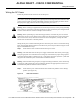
Cabling a Wireless Modem Card
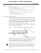
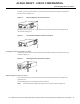
Attaching the RF Control Cables
Insert the RJ45 connector on the control cable into the Main Control connector port. If you will be
using the diversity option, use a second cable and attach it to the Diversity Control connector port.
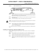
Attaching the IF and Monitor Cables
Connect one end of the IF signal cable to the Main PFP port. If you will be using the diversity option,
use a second cable and attach it to the Diversity PFP port.
(Optional) To use a spectrum analyzer to test or troubleshoot the signal on the modem card, attach
it to the Main Monitor port or Diversity Monitor port.
Cabling the 10 MHz Clock
To connect to a 10 MHz clock, connect an SMA to BMC adapter to the 10 MHz IN connector port.
Attach the clock cable’s BNC connector to the adapter.
This completes the procedure for installing a wireless modem card in the CiscouBR7200 series
router.
Installing a Power Feed Panel
A power feed panel can be mounted in a 19-inch rack or mounted on a wall. The unit can be
co-located with the router or placed near the outdoor unit, depending on your site requirements.
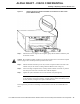
NoteAt least one rack unit space must exist between the uBR and the power feed panel or between
multiple power feed panels.
Rack-Mounting a Power Feed Panel
A power feed panel can be rack-mounted with either the front panel or the rear panel facing forward
depending on the cable handling requirements of your site, or in a center-mount telco rack. The
power LEDs are visible on both the front and rear panels.
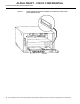
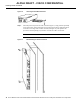
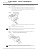
Attaching the Brackets
To install a power feed panel with the front panel facing forward, attach the brackets to both sides of
the unit as shown in Figure12.
Figure12 Bracket Installation - Front Panel Forward