
Installation Manual

CiscouBR7200 Series Universal Broadband Router Wireless Modem Card and Subsystem Installation and Configuration 19
Wiring the DC Power
ALPHA DRAFT - CISCO CONFIDENTIAL
Wiring the DC Power
Follow the procedures in this section to wire the DC power.
NoteThe color coding of DC-input power supply leads depends on the color coding of the DC
power source at your site. Typically, green or green/yellow is used for ground, black is used for +48V
(return), and red or white is used for –48V. Make certain the lead color coding you choose for the
DC-input power supply matches lead color coding at the DC power source.
WarningBefore working on equipment that is connected to power lines, remove jewelry (including
rings, necklaces, and watches). metal objects will heat up when connected to power and ground and
can cause serious burns or weld the metal object to the terminals.
WarningBefore performing any of the following procedures, ensure that the power is removed
from the DC circuit. To ensure that all power is OFF, locate the circuit breaker on the panel board
that services the DC circuit, switch the circuit breaker to the OFF position, and tape the switch
handle of the circuit breaker in the OFF position.
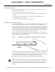
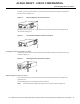
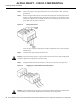
Wiring the DC power consists of attaching the wires of the DC power source to a removable wiring
block, then plugging that block into the connection on the power feed panel. Refer to Figure19 and
Figure20 and follow these steps.
Step1 Ensure that the leads are disconnected from the power source.
WarningThe Illustration shows the DC power supply terminal block. Wire the DC power supply
using the appropriate wire terminations at the wiring end, as illustrated. The proper wiring sequence
is ground to ground, positive to positive (line to +), and negative to negative (neutral to –). Note that
the ground wire should always be connected first and disconnected last.
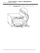
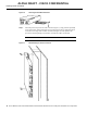
WarningWhen stranded wiring is required, use approved wiring terminations, such as closed-loop
or spade-type with upturned lugs. These terminations should be the appropriate size for the wires
and should clamp both the insulation and the conductor.
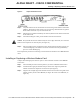
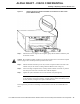
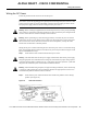
Step2 Ensure that the power switch for both the main and diversity ODU are in the OFF (0)
position. (See Figure18.)
Figure18 ODU Power Switches