
Installation Manual

20CiscouBR7200 Series Universal Broadband Router Wireless Modem Card and Subsystem Installation and Configuration
Installing a Power Feed Panel
ALPHA DRAFT - CISCO CONFIDENTIAL
Step3 Using a wire stripper, strip approximately 0.55 in. (14 mm) from the +48V, –48V and
ground leads.
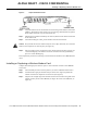
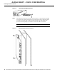
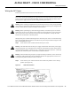
Step4 Insert the stripped ends of the wire in the removable wiring block according to the scheme
in Figure19. Figure19 illustrates the polarity of each connection. The connection on the
left is for the –48VDC wire, the middle connection is for safety ground. The connection
on the right is for the positive return wire.
Figure19 Wiring Connections
Secure the wires using the 1/8 in. blade screwdriver to tighten the screws in the top of the
terminal block.
Step5 Connect the DC input wiring to the DC source.
WarningFor personal safety, the green or green/yellow wire must connect to safety (earth) ground
at both the equipment and supply side of the DC wiring.
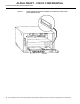
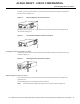
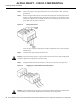
Step6 Plug the terminal block into the receptacle on the power feed panel. (See Figure20.)
Figure20 Plugging the Terminal Block into the Receptacle
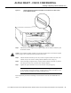
Warning
After wiring the DC power supply, remove the tape from the circuit breaker switch handle
and reinstate power by moving the handle of the circuit breaker to the ON position.