
Installation Manual


CiscouBR7200 Series Universal Broadband Router Wireless Modem Card and Subsystem Installation and Configuration 21
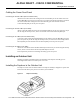
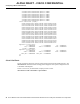
Cabling the Power Feed Panel
ALPHA DRAFT - CISCO CONFIDENTIAL
Cabling the Power Feed Panel
Connecting the Control Cables (from the Modem Card)
Attach the end of the control cable coming from the Control-Main port on the modem card to the
Control-Main/MC port on the power feed panel. If you will be using the diversity option, also attach
the second control cable coming from the Control-Diversity port on the modem card to the
Control-Diversity/MC port on the power feed panel.
Connecting the Control Cables (to the ODU)
Attach a cable with a DB9 connector to the Control-Main/ODU port on the power feed panel. If you
will be using the diversity feature, attach a second cable to the Control-Diversity/ODU port.
Connecting the IF Cables (from the Modem Card)
Connect the cables coming from the Main/PFP port of the modem card to the Main/MC port on the
power feed panel. If you will be using the diversity feature, also connect the cable coming from the
Diversity/PFP port of the modem card to the Diversity/MC port on the power feed panel.
Connecting the IF Cables (to the ODU)
Attach one end of the IF cable to the Main-ODU/Output connector. If you will be using the diversity
feature, attach a second cable to the Diversity-ODU/Output connector.
This completes the procedure for installing and cabling a power feed panel.
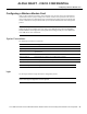
Installing an Outdoor Unit
Installing an outdoor unit (ODU) requires the installation of the duplexor assembly prior to
mounting the ODU either on an antenna pole or on a wall.
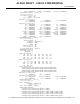
Installing the Duplexor in the Outdoor Unit
The duplexor acts as a filter for Tx/Rx isolation. The duplexor assembly is shipped as a separate unit
based on the RF channel plan you have selected for your installation.
Figure21 Duplexor Assembly