
Installation Manual


24CiscouBR7200 Series Universal Broadband Router Wireless Modem Card and Subsystem Installation and Configuration
Installing an Outdoor Unit
ALPHA DRAFT - CISCO CONFIDENTIAL
Step3
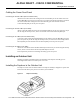
Figure27 Attaching the ODU to the Mounting Bracket
Step4
Step5
Cabling the Outdoor Unit
Cables leading to the ODU may require through-bulkhead connectors, lightning protection, or other
accessories. For more detailed information concerning these items, refer to the Cisco Wireless
Broadband Router Site Planning Guide.
Connecting the Control Cable
Connect the control cable from the power feed panel port marked Main/ODU to the Control
connector on the Main ODU. (See Figure7.)
If the diversity feature is being used, connect the control cable from the power feed panel port
marked Diversity/ODU to the Control connector on the Diversity ODU.
Connecting the IF Cable
NoteEnsure that the power switch (on the power feed panel) for both the Main and Diversity ODU
are in the OFF (0) position. (See Figure18.)
Connect the IF cable from the power feed panel port marked Main-ODU/Output to the IF Input
connector on the Main ODU. (See Figure7.)
If the diversity feature is being used, connect the IF cable from the power feed panel port marked
Diversity-ODU/Output to the IF Input connector on the Diversity ODU.
Connecting the Antenna Cable
Connect the RF cable leading to the Main antenna to the N connector on the duplexor on the Main
ODU. (See Figure7.)
If the diversity feature is being used, connect the RF cable leading to the Diversity antenna to the N
connector on the duplexor on the Diversity ODU.
This completes the procedure for installing and cabling an outdoor unit.