
Installation Manual

4 CiscouBR7200 Series Universal Broadband Router Wireless Modem Card and Subsystem Installation and Configuration
Wireless Modem Card and Subsystem Overview
ALPHA DRAFT - CISCO CONFIDENTIAL
Wireless Modem Card
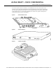
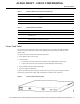
The wireless modem card provides the control and data interface to the system’s digital motherboard
and the radio frequency (RF) subsystem in the ODU. It also provides the up/down conversion from
baseband to intermediate frequency (IF).
Wireless modem cards consist of the following components:
• Main and diversity serial interface control connectors.
• 10 MHz external reference clock connection.
• Monitor and Power Feed Panel connectors (Main and Diversity)
• Light-emitting diodes (LEDs) which provide a visual indication of the state of the modem card,
as well as providing a mechanism by which specific condition can be easily noted.
NoteThe appearance and meaning of these LEDs can be displayed or modified using the show
interface and led commands. These commands are described in the section "Configuring a
Wireless Modem Card" on
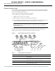
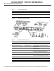
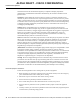
Figure4 shows the connectors and LEDs on the wireless modem card. Table1 describes the
functions of the connectors, and Table2 describes the functions of the LEDs.
Figure4 Wireless Modem Card Connectors and LEDs
Table1 Wireless Modem Card Connectors
Connector Type Function
Control - Main 8-pin RJ45 (female) Physical connection to Power Feed Panel for RF subsystem interface
control channel.
Control - Diversity 8-pin RJ45 (female) Physical connection to Power Feed Panel for RF subsystem interface
control channel (when diversity option is used).
10 MHz Input SMA (male) Connection for 10 MHz external reference clock.
Diversity - Monitor SMA (female) For connection to spectrum analyzer for test/troubleshooting purposes
(when diversity option is used).