
Installation Manual

CiscouBR7200 Series Universal Broadband Router Wireless Modem Card and Subsystem Installation and Configuration 5
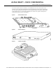
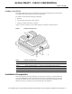
Power Feed Panel
ALPHA DRAFT - CISCO CONFIDENTIAL
Power Feed Panel
The power feed panel provides DC power and Tx/Rx and reference signals to the ODU. In addition,
the unit contains circuit breakers and secondary lightning protection circuitry for both the IF and
control cables.
The power feed panel consists of the following components:
• Power LEDs on front and rear panel
• Connector ports
— Coaxial cable connection to the wireless modem card and ODU (Main and Diversity)
— Control cable connection ports to modem card and ODU (Main and Diversity)
• Power ON/OFF switches (Main and Diversity)
• DC power supply terminal block
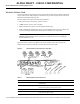
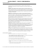
Figure5 shows the front panel and Figure6 shows the rear panel of the power feed panel. Table3
describes the functions of the LEDs. Table4 describes the functions of the connectors.
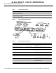
Figure5 Power Feed Panel (Front Panel)
Diversity - PFP SMA (female) 48 MHz reference, receive and transmit IF signals (when diversity option
is used).
Main - Monitor SMA (female) For connection to spectrum analyzer for test/troubleshooting purposes.
Main - PFP SMA (female) 48 MHz reference, receive and transmit IF signals.
Table2 Wireless Modem Card LEDs
LED Function
Carrier LED Indicates the state of the radio link. When lit, the radio link is up.
Out of Service LED Indicates the service availability of the radio link. When lit, the radio link is still up, but not
available for use.
Minor Alarm LED When lit, indicates the occurrence of a minor alarm in the radio subsystem. The link is
degraded and may need maintenance action.
Major Alarm LED When lit, indicates the occurrence of a major alarm in the radio subsystem. The link is down.
Table1 Wireless Modem Card Connectors (continued)
Connector Type Function