
Installation Manual

6 CiscouBR7200 Series Universal Broadband Router Wireless Modem Card and Subsystem Installation and Configuration
Wireless Modem Card and Subsystem Overview
ALPHA DRAFT - CISCO CONFIDENTIAL
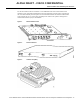
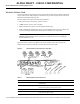
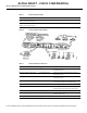
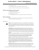
Figure6 Power Feed Panel (Rear Panel)
Table3 Power Feed Panel LEDs
LED Function
Main Power On
(visible on front and rear panel)
When lit, indicates that there is power going to the main ODU.
Diversity Power On
(visible on front and rear panel)
When lit, indicates that there is power going to the diversity ODU.
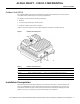
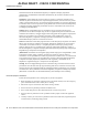
Table4 Power Feed Panel Connectors
Connector Type Function
Main ODU Control DB9 (female) Physical connection to the main ODU for RF
subsystem interface.
Main MC (modem card) Control 8-pin RJ45 (female) Physical connection for RF subsystem interface
from modem card.
Diversity ODU Control DB9 (female) Physical connection to the diversity ODU for RF
subsystem interface.
Diversity MC (modem card) Control 8-pin RJ45 (female) Physical connection for RF subsystem interface
from modem card (if diversity option used).
Diversity ODU Output N-Type (female) Provides signal and power to the diversity ODU.
Diversity MC (modem card) SMA (female) 48 MHz reference, receive and transmit IF signals
from the modem card (if diversity option used).
Main ODU Output N-Type (female) Provides signal and power to the main ODU.
Main MC (modem card) SMA (female) 48 MHz reference, receive and transmit IF signals
from the modem card.
DC Power Input Pluggable terminal block Power source for the main and diversity ODUs.