
Installation Manual

8 CiscouBR7200 Series Universal Broadband Router Wireless Modem Card and Subsystem Installation and Configuration
Installation Prerequisites
ALPHA DRAFT - CISCO CONFIDENTIAL
Parts and Tools
The following sections describe the parts and tools required to install each of the components. If you
need more detailed information regarding cables or connectors, refer to the Cisco Wireless
Broadband Router Site Planning Guide.
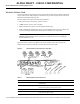
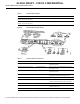
Wireless Modem Card
You need the following tools and parts to remove and replace a wireless modem card. If you need
additional equipment, contact a service representative for ordering information.
• New wireless modem card
• No.2 Phillips screwdriver
• 5/16 in. open end wrench
• Your own ESD-prevention equipment or the disposable grounding wrist strap included with all
upgrade kits, FRUs, and spares
• Antistatic mat or surface
• Static shielding bag
• Cable with RJ45 connectors and coaxial cable with SMA connectors for connections between the
modem card and the power feed panel. (Standard sets of these cables can be purchased from
Cisco.)
• SMA (male) to BNC (male) adapter cable and coaxial cable for cabling the 10 MHz clock.
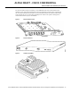
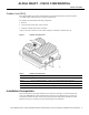
Power Feed Panel
You need the following tools and parts to install the power feed panel in an equipment rack. If you
need additional equipment, contact a service representative for ordering information.
• Power feed panel
• No.2 Phillips screwdriver
• Bracket kit (provided)
• Rack mount or wall mount screws
• 1/8 in. blade screwdriver
• 5/16 in. open end wrench
• Cables with N-type (male) connectors for IF control
• Cables with DB9 (male) and Lemo (male) connectors (Lemo connector provided)
• 48VDC power supply
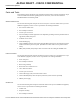
Outdoor Unit
You need the following tools and parts to install the outdoor unit. If you need additional equipment,
contact a service representative for ordering information.
• Outdoor unit
• Duplexor assembly
• No.2 Phillips screwdriver