
- Cisco WAN Modeling Tools User Guide
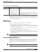
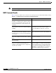

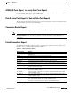
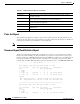
Table Of Contents
- Cisco WAN Modeling Tools User Guide
- Contents
- Related CWM and Switch Documentation
- Obtaining Documentation
- Documentation Feedback
- Cisco Product Security Overview
- Obtaining Technical Assistance
- Obtaining Additional Publications and Information
- Cisco WAN Modeling Tools Overview
- Functionality of the NMT
- Cisco Products Supported by the NMT
- Basic Usage/Charter Functionality
- Gaps
- Data Translation Tools
- System Requirements
- Installing the NMT
- Upgrading the NMT Software
- Starting the NMT
- Removing NMT
- Installing a Cisco WAN Modeling Tools Sub-application
- Removing Sub-applications
- Troubleshooting NMT Installation
- NMT Startup
- NMT Menu Bar
- File Menu
- Display Menu
- Keyboard Commands
- Modeling Processes
- Error Checking
- Troubleshooting NMT
- General Table Information
- Sites Table
- Links Table
- Link Special Cases
- Voice Table
- Data Table
- Bursty Table
- Interface Table
- Feeder Table
- Card Table
- Groups and Network Table
- Nodes Table
- Network Settings
- Model Options
- Feeders
- Obsolete Products
- FastPAD
- Port Concentrator
- Tiered Networks
- Using the Route Command
- AutoRoute
- AutoRoute Least Cost Routing
- PNNI Routing
- Fail Analysis Command
- Build Sites Command
- Optimize Command
- NMT Command Results
- Site Report
- Link Report
- Network Summary Report
- Link Load Report
- ATM & FR Ports Report (or Bursty Data Ports Report)
- Data & Voice Ports Report (or Voice & Data Ports Report)
- Connection Routes Report
- Failed Connections Report
- Parts List Report
- Resource Report/Card Statistics Report
- PNNI Topology Report
- View Summary
- Using the Map Tool
- NMT Map Startup
- Navigating Though a Network View
- Obtaining Link Information - Physical Links
- Obtaining Link Information - Logical Links
- Zooming the Map
- Panning the Map
- Map Color Coding
- Controlling Map Displays in NMT
- NMT Map Main Menu
- Adding New Groups
- Adding Nodes to Existing Groups
- Deleting Groups
- Deleting Nodes or Groups from Existing Groups
- Saving Your Work
- Retrieving Map Data Into NMT
- Using the Map Tool with Fail Analysis
- Using the Map Tool to Analyze Traffic Levels
- Fields Addressed by CET
- Using the CET
- Other CET Commands
- Troubleshooting CET
- Remote CET Extracts
- Translating Between NMT and WANDL Formats
- NMT to Microsoft Excel
- Microsoft Excel to NMT
- Usage Review
- SSI TroubleShooting
- CND PC Import Utilities
- Index

6-4
Cisco WAN Modeling Tools Guide
OL-10426-01, Rev. A0
Chapter 6 NMT Reports
Parts List Report
The parts list report lists parts required to provision the modeled network. The parts included are the
chassis, front cards, back cards, and special shelves and units. Cables and optional parts are usually not
included in the parts list report. Bundles are used if applicable.
Note The Parts List Report is output in DBF format.
Resource Report/Card Statistics Report
The Resource Report/Card Statistics Report displays the card cage for each system unit, and a brief
listing of used and available ports. The card statistics report is the second part of the resource report.
Release 15 of the Cisco WAN Modeling Tools models the UXM card, and has a new card statistics report
for tracking the UBU usage of this and other cards. Below is a card statistics report for a two IGX
networks with 295 ATF = FR interworking connections between the nodes, each MIR=64K, PIR=256K.
------------------------- Card Statistics ----------------------------
Node: ATM_Side Type: IGX-8 Bus Used: 40 UBUs out of 584
Slot Front Back Type PVCs Port UBU/PS Card Specific
Stat Used Allc/Used/Max
1 A NPM 2 2 2
2 S NPM
3 A UXM 3T3 Trunk 295 1 25 13 184 FPL=8%, GWL=2%
4 A UXM 3T3 Line 295 1 13 13 184 FPL=8%, GWL=2%
Legends:
FPL - Fast Packet Load : Percent of FP bus load / Total bus load.
GWL - Gateway Module Load : Percent of FP bus load / Max FP bus load.
====================================================================
Node: FR_Side Type: IGX-8 Bus Used: 118 UBUs out of 584
Slot Front Back Type PVCs Port UBU/PS Card Specific
Stat Used Allc/Used/Max
1 A NPM 2 2 2
2 S NPM
3 A UXM 3T3 Trunk 295 1 60 60 184 FPL=100%, GWL=100%
Too Big Delay Connection cannot be routed without exceeding the maximum delay. (This pertains to
AutoRoute networks.)
No CellBase Path Connection cannot be routed without being converted to FastPackets on older equipment,
but the connection is not permitted to be converted to FastPackets.
No ATM Path ATM connection cannot be routed without using trunks that do not support ATM types of
load (on older Fastpacket equipment).
No COS Path No path to support Class of Service connections. (This pertains to PNNI networks.)
Transit Rstr No path that would not have via nodes configured as transit restricted. (This pertains to
PNNI networks.)
Media Restricted Connection can only be routed using a restricted media (for instance, a satellite link).
Table 6-1 Failed Connection Reasons (continued)
Reason String Meaning