
- Cisco WAN Modeling Tools User Guide
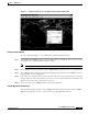


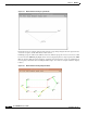
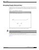
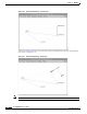
Table Of Contents
- Cisco WAN Modeling Tools User Guide
- Contents
- Related CWM and Switch Documentation
- Obtaining Documentation
- Documentation Feedback
- Cisco Product Security Overview
- Obtaining Technical Assistance
- Obtaining Additional Publications and Information
- Cisco WAN Modeling Tools Overview
- Functionality of the NMT
- Cisco Products Supported by the NMT
- Basic Usage/Charter Functionality
- Gaps
- Data Translation Tools
- System Requirements
- Installing the NMT
- Upgrading the NMT Software
- Starting the NMT
- Removing NMT
- Installing a Cisco WAN Modeling Tools Sub-application
- Removing Sub-applications
- Troubleshooting NMT Installation
- NMT Startup
- NMT Menu Bar
- File Menu
- Display Menu
- Keyboard Commands
- Modeling Processes
- Error Checking
- Troubleshooting NMT
- General Table Information
- Sites Table
- Links Table
- Link Special Cases
- Voice Table
- Data Table
- Bursty Table
- Interface Table
- Feeder Table
- Card Table
- Groups and Network Table
- Nodes Table
- Network Settings
- Model Options
- Feeders
- Obsolete Products
- FastPAD
- Port Concentrator
- Tiered Networks
- Using the Route Command
- AutoRoute
- AutoRoute Least Cost Routing
- PNNI Routing
- Fail Analysis Command
- Build Sites Command
- Optimize Command
- NMT Command Results
- Site Report
- Link Report
- Network Summary Report
- Link Load Report
- ATM & FR Ports Report (or Bursty Data Ports Report)
- Data & Voice Ports Report (or Voice & Data Ports Report)
- Connection Routes Report
- Failed Connections Report
- Parts List Report
- Resource Report/Card Statistics Report
- PNNI Topology Report
- View Summary
- Using the Map Tool
- NMT Map Startup
- Navigating Though a Network View
- Obtaining Link Information - Physical Links
- Obtaining Link Information - Logical Links
- Zooming the Map
- Panning the Map
- Map Color Coding
- Controlling Map Displays in NMT
- NMT Map Main Menu
- Adding New Groups
- Adding Nodes to Existing Groups
- Deleting Groups
- Deleting Nodes or Groups from Existing Groups
- Saving Your Work
- Retrieving Map Data Into NMT
- Using the Map Tool with Fail Analysis
- Using the Map Tool to Analyze Traffic Levels
- Fields Addressed by CET
- Using the CET
- Other CET Commands
- Troubleshooting CET
- Remote CET Extracts
- Translating Between NMT and WANDL Formats
- NMT to Microsoft Excel
- Microsoft Excel to NMT
- Usage Review
- SSI TroubleShooting
- CND PC Import Utilities
- Index
6-7
Cisco WAN Modeling Tools Guide
OL-10426-01, Rev. A0
Chapter 6 NMT Reports
Using the Map Tool
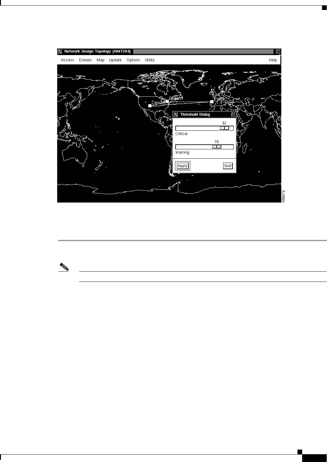
Figure 6-1 Example of Network Topology Map Showing Threshold Dialog Box
Creating a Graphical Display
To create a graphical display of a new configuration, perform the following steps:
Step 1 Select Map from the Display menu and drag the Map window to a suitable location on your screen. It
may take several seconds for the Map window to display.
Note Select Map tool menus by using the left mouse button, except where noted.
Step 2 Choose Update from the menu bar and click on Update Map to import the most recent configuration.
Step 3 Choose Map from the menu bar in the Network Design Topology window and click Select to choose a
map appropriate to your configuration.
Step 4 Drag each node to its approximate location on the map. The node icons (colored squares) are stacked in
the upper left corner of the window. Place your cursor over a node, hold down the left mouse button, and
drag the node into place. Repeat this step for each node.
Step 5 To save your map, choose Utility from the menu bar and select Save.
Using the Map Tool with Fail Analysis
After performing a failure analysis, click on Update in the map window menu bar, and select Update
Map. Any site that did not reroute a connection for any of the link failures turns red.