
- Cisco WAN Modeling Tools User Guide
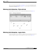
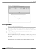
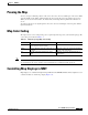
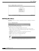
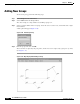
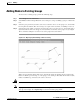
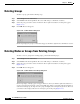
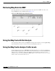
Table Of Contents
- Cisco WAN Modeling Tools User Guide
- Contents
- Related CWM and Switch Documentation
- Obtaining Documentation
- Documentation Feedback
- Cisco Product Security Overview
- Obtaining Technical Assistance
- Obtaining Additional Publications and Information
- Cisco WAN Modeling Tools Overview
- Functionality of the NMT
- Cisco Products Supported by the NMT
- Basic Usage/Charter Functionality
- Gaps
- Data Translation Tools
- System Requirements
- Installing the NMT
- Upgrading the NMT Software
- Starting the NMT
- Removing NMT
- Installing a Cisco WAN Modeling Tools Sub-application
- Removing Sub-applications
- Troubleshooting NMT Installation
- NMT Startup
- NMT Menu Bar
- File Menu
- Display Menu
- Keyboard Commands
- Modeling Processes
- Error Checking
- Troubleshooting NMT
- General Table Information
- Sites Table
- Links Table
- Link Special Cases
- Voice Table
- Data Table
- Bursty Table
- Interface Table
- Feeder Table
- Card Table
- Groups and Network Table
- Nodes Table
- Network Settings
- Model Options
- Feeders
- Obsolete Products
- FastPAD
- Port Concentrator
- Tiered Networks
- Using the Route Command
- AutoRoute
- AutoRoute Least Cost Routing
- PNNI Routing
- Fail Analysis Command
- Build Sites Command
- Optimize Command
- NMT Command Results
- Site Report
- Link Report
- Network Summary Report
- Link Load Report
- ATM & FR Ports Report (or Bursty Data Ports Report)
- Data & Voice Ports Report (or Voice & Data Ports Report)
- Connection Routes Report
- Failed Connections Report
- Parts List Report
- Resource Report/Card Statistics Report
- PNNI Topology Report
- View Summary
- Using the Map Tool
- NMT Map Startup
- Navigating Though a Network View
- Obtaining Link Information - Physical Links
- Obtaining Link Information - Logical Links
- Zooming the Map
- Panning the Map
- Map Color Coding
- Controlling Map Displays in NMT
- NMT Map Main Menu
- Adding New Groups
- Adding Nodes to Existing Groups
- Deleting Groups
- Deleting Nodes or Groups from Existing Groups
- Saving Your Work
- Retrieving Map Data Into NMT
- Using the Map Tool with Fail Analysis
- Using the Map Tool to Analyze Traffic Levels
- Fields Addressed by CET
- Using the CET
- Other CET Commands
- Troubleshooting CET
- Remote CET Extracts
- Translating Between NMT and WANDL Formats
- NMT to Microsoft Excel
- Microsoft Excel to NMT
- Usage Review
- SSI TroubleShooting
- CND PC Import Utilities
- Index

8-7
Cisco WAN Modeling Tools Guide
OL-10426-01, Rev. A0
Chapter 8 NMT Map
Panning the Map
Panning the Map
To move a map to a different position on the screen, move the cursor to a blank spot on the screen. Hold
down the middle mouse button while dragging the cursor in the direction you want the map to move.
When you release the mouse button, the nodes, links, and background map shift in that direction on
screen.
To return to the map to its original position, move the cursor to a blank spot on the map and click the
right mouse button.
Map Color Coding
The map tool uses color coding to help you recognize important aspects of your network topology. The
color coding is described in Table 8-1.
Note The colors of the logical nodes (groups of nodes) and the links displayed with thick lines (multiple links)
are determined by the worst condition of the individual nodes or links that make up the set.
Controlling Map Displays in NMT
Map displays are controlled through the Report Menu in the NMT Main Menu. The Set Options screen
contains variables to control map output. (Figure 8-8).
Table 8-1 Network Topology Map Color Coding
Color Node Link
Green Node is functioning normally (all
connections have been routed).
Link traffic is below the warning threshold.
Yellow Node is a hub node, and some of its feeders are
not shown.
Link traffic is above the warning threshold but
below the critical
threshold.
Red
Not all connections at this node could
route.
Link
traffic exceeds the critical threshold, or
link has failed.