
- Cisco WAN Modeling Tools User Guide
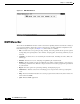
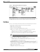
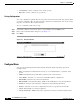
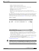
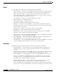
Table Of Contents
- Cisco WAN Modeling Tools User Guide
- Contents
- Related CWM and Switch Documentation
- Obtaining Documentation
- Documentation Feedback
- Cisco Product Security Overview
- Obtaining Technical Assistance
- Obtaining Additional Publications and Information
- Cisco WAN Modeling Tools Overview
- Functionality of the NMT
- Cisco Products Supported by the NMT
- Basic Usage/Charter Functionality
- Gaps
- Data Translation Tools
- System Requirements
- Installing the NMT
- Upgrading the NMT Software
- Starting the NMT
- Removing NMT
- Installing a Cisco WAN Modeling Tools Sub-application
- Removing Sub-applications
- Troubleshooting NMT Installation
- NMT Startup
- NMT Menu Bar
- File Menu
- Display Menu
- Keyboard Commands
- Modeling Processes
- Error Checking
- Troubleshooting NMT
- General Table Information
- Sites Table
- Links Table
- Link Special Cases
- Voice Table
- Data Table
- Bursty Table
- Interface Table
- Feeder Table
- Card Table
- Groups and Network Table
- Nodes Table
- Network Settings
- Model Options
- Feeders
- Obsolete Products
- FastPAD
- Port Concentrator
- Tiered Networks
- Using the Route Command
- AutoRoute
- AutoRoute Least Cost Routing
- PNNI Routing
- Fail Analysis Command
- Build Sites Command
- Optimize Command
- NMT Command Results
- Site Report
- Link Report
- Network Summary Report
- Link Load Report
- ATM & FR Ports Report (or Bursty Data Ports Report)
- Data & Voice Ports Report (or Voice & Data Ports Report)
- Connection Routes Report
- Failed Connections Report
- Parts List Report
- Resource Report/Card Statistics Report
- PNNI Topology Report
- View Summary
- Using the Map Tool
- NMT Map Startup
- Navigating Though a Network View
- Obtaining Link Information - Physical Links
- Obtaining Link Information - Logical Links
- Zooming the Map
- Panning the Map
- Map Color Coding
- Controlling Map Displays in NMT
- NMT Map Main Menu
- Adding New Groups
- Adding Nodes to Existing Groups
- Deleting Groups
- Deleting Nodes or Groups from Existing Groups
- Saving Your Work
- Retrieving Map Data Into NMT
- Using the Map Tool with Fail Analysis
- Using the Map Tool to Analyze Traffic Levels
- Fields Addressed by CET
- Using the CET
- Other CET Commands
- Troubleshooting CET
- Remote CET Extracts
- Translating Between NMT and WANDL Formats
- NMT to Microsoft Excel
- Microsoft Excel to NMT
- Usage Review
- SSI TroubleShooting
- CND PC Import Utilities
- Index

3-7
Cisco WAN Modeling Tools Guide
OL-10426-01, Rev. A0
Chapter 3 Using the NMT
Display Menu
Defaults
To create your own defaults for any or all tables, create a CNF file and call it DEFAULTS. Save it to your
working directory. Any new records you create for a field in any table will have the values of the first
entry in that table. To use an existing file for your defaults, select it in the edit options window.
Note This option does not apply to the site names field in any table.
Execute Menu
You can access the following commands from the File menu in the Network Design Tools window:
• Route—Routes traffic over specified links
• Fail Analysis...—Performs failure analysis on the lines and forces NMT to create alternate routes.
• Build Sites—Provisions the nodes without routing.
• Optimize—Uses selected links to create a least cost topology.
Display Menu
You can access the following commands from the File menu in the Network Design Tools window:
Sites Displays customer site information.
Links Displays a list of links in the current network.
Network Summary Displays summaries of the current network costs and routing status.
Total Links Load Displays static load estimates by traffic type for each link in the network.
ATM & F r Ports Site name, connection type (for example, FRM-V35), slot number, port number,
port speed (cells or packets per second), SUM MIN (port load).
Data & Voice Ports Site name, connection type (for example, SDP-V35), slot number, port number,
port speed.
Connection Routes Connection to/from, number of connections, connection type (for example, FR,
56), path number of hops, delay time in msec for voice and NTS connections.
Failed Connections Displays failed connections and connections that have not been routed.
Parts List Listed by site, including part number, description, quantity, cost per site.
Resources Graphical display of each node’s card cage showing front cards and back cards.
PNNI Topology Displays PNNI logical links.
User Message View or clear the message log. You can also view the message log by entering
<Ctrl> W.
Map Network topology map.