
- Cisco WAN Modeling Tools User Guide
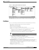
Table Of Contents
- Cisco WAN Modeling Tools User Guide
- Contents
- Related CWM and Switch Documentation
- Obtaining Documentation
- Documentation Feedback
- Cisco Product Security Overview
- Obtaining Technical Assistance
- Obtaining Additional Publications and Information
- Cisco WAN Modeling Tools Overview
- Functionality of the NMT
- Cisco Products Supported by the NMT
- Basic Usage/Charter Functionality
- Gaps
- Data Translation Tools
- System Requirements
- Installing the NMT
- Upgrading the NMT Software
- Starting the NMT
- Removing NMT
- Installing a Cisco WAN Modeling Tools Sub-application
- Removing Sub-applications
- Troubleshooting NMT Installation
- NMT Startup
- NMT Menu Bar
- File Menu
- Display Menu
- Keyboard Commands
- Modeling Processes
- Error Checking
- Troubleshooting NMT
- General Table Information
- Sites Table
- Links Table
- Link Special Cases
- Voice Table
- Data Table
- Bursty Table
- Interface Table
- Feeder Table
- Card Table
- Groups and Network Table
- Nodes Table
- Network Settings
- Model Options
- Feeders
- Obsolete Products
- FastPAD
- Port Concentrator
- Tiered Networks
- Using the Route Command
- AutoRoute
- AutoRoute Least Cost Routing
- PNNI Routing
- Fail Analysis Command
- Build Sites Command
- Optimize Command
- NMT Command Results
- Site Report
- Link Report
- Network Summary Report
- Link Load Report
- ATM & FR Ports Report (or Bursty Data Ports Report)
- Data & Voice Ports Report (or Voice & Data Ports Report)
- Connection Routes Report
- Failed Connections Report
- Parts List Report
- Resource Report/Card Statistics Report
- PNNI Topology Report
- View Summary
- Using the Map Tool
- NMT Map Startup
- Navigating Though a Network View
- Obtaining Link Information - Physical Links
- Obtaining Link Information - Logical Links
- Zooming the Map
- Panning the Map
- Map Color Coding
- Controlling Map Displays in NMT
- NMT Map Main Menu
- Adding New Groups
- Adding Nodes to Existing Groups
- Deleting Groups
- Deleting Nodes or Groups from Existing Groups
- Saving Your Work
- Retrieving Map Data Into NMT
- Using the Map Tool with Fail Analysis
- Using the Map Tool to Analyze Traffic Levels
- Fields Addressed by CET
- Using the CET
- Other CET Commands
- Troubleshooting CET
- Remote CET Extracts
- Translating Between NMT and WANDL Formats
- NMT to Microsoft Excel
- Microsoft Excel to NMT
- Usage Review
- SSI TroubleShooting
- CND PC Import Utilities
- Index

3-8
Cisco WAN Modeling Tools Guide
OL-10426-01, Rev. A0
Chapter 3 Using the NMT
Display Menu
Report Menu
Use the Report menu to define, generate, display, and save reports. The menu contains the following
options:
Define Selects which tables to include in a report. Figure 2-5 shows the Define Report
window. In this window you can specify the contents of the report and also add
a report header. Enter one of the following options:
Y—includes a report in a report file.
N—do not include a report in the report file.
X—do not generate a report (saves execution time).
Generate Names and generates a report.
View Selects a report to display.
Erase Deletes a report from the current directory.
Path Sets the directory path.
Set Options Specifies the following report variables:
• Price Option— Enter 0 for normal pricing. Enter a number from 1 through 5
to specify number of years in lease.
• Detail Reports— Enter Y to generate Bursty Link Load Reports. Enter N to
exclude Bursty Link Load Reports.
• Output DBF Reports— Enter Y to create a report in DBF and text format.
Enter N to create report only in text format.
• Output Pref Rte — Sets Preferred routes. Y to output a file of preferred
routes that can be inserted into switch CLI commands to create those routes.
• Bundle Connections — Y will keep connections bundled by routing
properties in the reports to reduce the size. N will expand reports for each
individual connection.
• Output Map Info —Y will write the information from a NMT command to
be input into the MAP graphical display. N will not to reduce execution time.
• Map Site Feeders — Y will display all feeder sites and their links on the map,
N will display only routing nodes and links.
• Map MultiNode Sites — Y will display each switch in the case where NMT
generated addition switches at a site, N will display only one marker for site
table entry.