
- Cisco WAN Modeling Tools User Guide
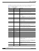

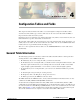
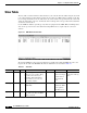
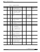
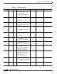
Table Of Contents
- Cisco WAN Modeling Tools User Guide
- Contents
- Related CWM and Switch Documentation
- Obtaining Documentation
- Documentation Feedback
- Cisco Product Security Overview
- Obtaining Technical Assistance
- Obtaining Additional Publications and Information
- Cisco WAN Modeling Tools Overview
- Functionality of the NMT
- Cisco Products Supported by the NMT
- Basic Usage/Charter Functionality
- Gaps
- Data Translation Tools
- System Requirements
- Installing the NMT
- Upgrading the NMT Software
- Starting the NMT
- Removing NMT
- Installing a Cisco WAN Modeling Tools Sub-application
- Removing Sub-applications
- Troubleshooting NMT Installation
- NMT Startup
- NMT Menu Bar
- File Menu
- Display Menu
- Keyboard Commands
- Modeling Processes
- Error Checking
- Troubleshooting NMT
- General Table Information
- Sites Table
- Links Table
- Link Special Cases
- Voice Table
- Data Table
- Bursty Table
- Interface Table
- Feeder Table
- Card Table
- Groups and Network Table
- Nodes Table
- Network Settings
- Model Options
- Feeders
- Obsolete Products
- FastPAD
- Port Concentrator
- Tiered Networks
- Using the Route Command
- AutoRoute
- AutoRoute Least Cost Routing
- PNNI Routing
- Fail Analysis Command
- Build Sites Command
- Optimize Command
- NMT Command Results
- Site Report
- Link Report
- Network Summary Report
- Link Load Report
- ATM & FR Ports Report (or Bursty Data Ports Report)
- Data & Voice Ports Report (or Voice & Data Ports Report)
- Connection Routes Report
- Failed Connections Report
- Parts List Report
- Resource Report/Card Statistics Report
- PNNI Topology Report
- View Summary
- Using the Map Tool
- NMT Map Startup
- Navigating Though a Network View
- Obtaining Link Information - Physical Links
- Obtaining Link Information - Logical Links
- Zooming the Map
- Panning the Map
- Map Color Coding
- Controlling Map Displays in NMT
- NMT Map Main Menu
- Adding New Groups
- Adding Nodes to Existing Groups
- Deleting Groups
- Deleting Nodes or Groups from Existing Groups
- Saving Your Work
- Retrieving Map Data Into NMT
- Using the Map Tool with Fail Analysis
- Using the Map Tool to Analyze Traffic Levels
- Fields Addressed by CET
- Using the CET
- Other CET Commands
- Troubleshooting CET
- Remote CET Extracts
- Translating Between NMT and WANDL Formats
- NMT to Microsoft Excel
- Microsoft Excel to NMT
- Usage Review
- SSI TroubleShooting
- CND PC Import Utilities
- Index

CHAPTER
4-1
Cisco WAN Modeling Tools Guide
OL-10426-01, Rev. A0
4
Configuration Tables and Fields
This chapter describes the fields in the tables accessed through the Configure menu.These tables
describe sites, links, traffic types, and more. This data can be created and edited with the NMT, or
imported into the tables from other systems.
Network topologies are defined by sets of tables. Each table entry defines a network element, and each
table field defines a specific characteristic of that element.
The Site table, which defines the switch locations, is the only mandatory table. In the other tables, you
usually only need to define the site name field in the other tables. You can use the NMT default values
in almost all cases to get familiar with the modeling process.
There is no order requirements in these tables. Use the CONFIG/UTILITY to sort the table entries
automatically.
General Table Information
The following legend refers to the Notes column in the tables that follow. Refer to this legend when
deciding whether to edit an NMT default value.
• M—Mandatory. If you are revising this table, you must revise this field.
• E—Evaluate. If you are revising this table, you should consider revising this field. For instance, this
field may require modification if you are working with a tiered network, an ISP, a network that
requires highly regulated bandwidth, or one in which cost factors must be highly regulated.
• O—Optional. If you are revising this table, you need not revise this field. Defaults are generally
suitable.
• P—Parts. Required for generating an accurate parts list.
• H—Help. Press F12 or the Help key to call up a list of choices.
• X—Entries generated by the NMT that cannot be edited.
The DBF column lists the DBF field name, and any additional translation information. There are also
columns for the CET (CWM) and TPI (WANDL) translations.
An asterisk in the Configuration Extraction Tool (CET) column or the Third Party Interface (TPI)
column indicates that the CET and/or the TPI supports a particular field. For instance, the CET extracts
site names from the Cisco Wan Manager (CWM) database, so there is an asterisk in the site row of the
CET column in Table 4-1. The asterisk indicates that the field is translated as described in the legend
above. If the translation is more complex, it is described in the CET or TPI column.