
- Cisco WAN Modeling Tools User Guide
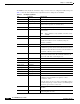

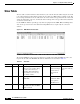
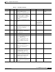
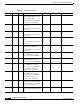
Table Of Contents
- Cisco WAN Modeling Tools User Guide
- Contents
- Related CWM and Switch Documentation
- Obtaining Documentation
- Documentation Feedback
- Cisco Product Security Overview
- Obtaining Technical Assistance
- Obtaining Additional Publications and Information
- Cisco WAN Modeling Tools Overview
- Functionality of the NMT
- Cisco Products Supported by the NMT
- Basic Usage/Charter Functionality
- Gaps
- Data Translation Tools
- System Requirements
- Installing the NMT
- Upgrading the NMT Software
- Starting the NMT
- Removing NMT
- Installing a Cisco WAN Modeling Tools Sub-application
- Removing Sub-applications
- Troubleshooting NMT Installation
- NMT Startup
- NMT Menu Bar
- File Menu
- Display Menu
- Keyboard Commands
- Modeling Processes
- Error Checking
- Troubleshooting NMT
- General Table Information
- Sites Table
- Links Table
- Link Special Cases
- Voice Table
- Data Table
- Bursty Table
- Interface Table
- Feeder Table
- Card Table
- Groups and Network Table
- Nodes Table
- Network Settings
- Model Options
- Feeders
- Obsolete Products
- FastPAD
- Port Concentrator
- Tiered Networks
- Using the Route Command
- AutoRoute
- AutoRoute Least Cost Routing
- PNNI Routing
- Fail Analysis Command
- Build Sites Command
- Optimize Command
- NMT Command Results
- Site Report
- Link Report
- Network Summary Report
- Link Load Report
- ATM & FR Ports Report (or Bursty Data Ports Report)
- Data & Voice Ports Report (or Voice & Data Ports Report)
- Connection Routes Report
- Failed Connections Report
- Parts List Report
- Resource Report/Card Statistics Report
- PNNI Topology Report
- View Summary
- Using the Map Tool
- NMT Map Startup
- Navigating Though a Network View
- Obtaining Link Information - Physical Links
- Obtaining Link Information - Logical Links
- Zooming the Map
- Panning the Map
- Map Color Coding
- Controlling Map Displays in NMT
- NMT Map Main Menu
- Adding New Groups
- Adding Nodes to Existing Groups
- Deleting Groups
- Deleting Nodes or Groups from Existing Groups
- Saving Your Work
- Retrieving Map Data Into NMT
- Using the Map Tool with Fail Analysis
- Using the Map Tool to Analyze Traffic Levels
- Fields Addressed by CET
- Using the CET
- Other CET Commands
- Troubleshooting CET
- Remote CET Extracts
- Translating Between NMT and WANDL Formats
- NMT to Microsoft Excel
- Microsoft Excel to NMT
- Usage Review
- SSI TroubleShooting
- CND PC Import Utilities
- Index

4-3
Cisco WAN Modeling Tools Guide
OL-10426-01, Rev. A0
Chapter 4 Configuration Tables and Fields
Sites Table
Site Type Switch M/H Function of platform at the site.
Can be a switch, feeder,
controller or a stand alone unit.
STYPE * Restrictions imposed
on links
SwRel O Software release of the
switch(es) at this site. If blank,
this field defaults to the global
value defined in the Model
Settings.
SW_REL *
PC Blank P Processor card. If Blank, use the
latest.
NPC *
From card table.
Default value used
until Release 9.1.
Red Y P Redundancy. Y—site has
redundant components. N—site
does not have redundant
components.
RED
Cab T1 P Cabinet. Specifies cabinet type
(T1—American or Far Eastern;
E1—European).
CABINET
Power A P/H Power supply. AC_DC
DFM N O Data Frame Multiplexing.
Y—site uses DFM. N—site does
not use DFM. If a data
connection terminating at this
site has a DFM setting of Y, it
takes precedence over the site
setting.
DFM
S/R P O Save/Restore. Y—site uses
save/restore configuration
software. N—site does not use
save/restore configuration
software.
S_R
FrFac 1.14 O Frame Relay Factor. Multiplier to
account for frame overhead on
the IPX Mux Bus. (The 1.14
default is an IPX legacy setting.)
FR_FAC
Bundle 24 O Maximum number of
connections that can be routed
simultaneously. Default is 32;
choose between 1 and 29.
BUNDLE
Modem% 0 E Percentage of modem traffic on
voice connections originating at
this site.
MODEM_P
CT
Table 4-1 .Site Table (continued)
Field Defaults Notes Description and Comments DBF CET TPI