
- Cisco WAN Modeling Tools User Guide
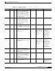
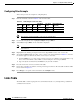
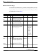
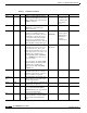

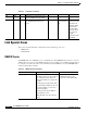
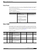
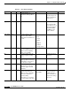
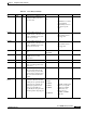
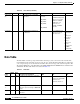
Table Of Contents
- Cisco WAN Modeling Tools User Guide
- Contents
- Related CWM and Switch Documentation
- Obtaining Documentation
- Documentation Feedback
- Cisco Product Security Overview
- Obtaining Technical Assistance
- Obtaining Additional Publications and Information
- Cisco WAN Modeling Tools Overview
- Functionality of the NMT
- Cisco Products Supported by the NMT
- Basic Usage/Charter Functionality
- Gaps
- Data Translation Tools
- System Requirements
- Installing the NMT
- Upgrading the NMT Software
- Starting the NMT
- Removing NMT
- Installing a Cisco WAN Modeling Tools Sub-application
- Removing Sub-applications
- Troubleshooting NMT Installation
- NMT Startup
- NMT Menu Bar
- File Menu
- Display Menu
- Keyboard Commands
- Modeling Processes
- Error Checking
- Troubleshooting NMT
- General Table Information
- Sites Table
- Links Table
- Link Special Cases
- Voice Table
- Data Table
- Bursty Table
- Interface Table
- Feeder Table
- Card Table
- Groups and Network Table
- Nodes Table
- Network Settings
- Model Options
- Feeders
- Obsolete Products
- FastPAD
- Port Concentrator
- Tiered Networks
- Using the Route Command
- AutoRoute
- AutoRoute Least Cost Routing
- PNNI Routing
- Fail Analysis Command
- Build Sites Command
- Optimize Command
- NMT Command Results
- Site Report
- Link Report
- Network Summary Report
- Link Load Report
- ATM & FR Ports Report (or Bursty Data Ports Report)
- Data & Voice Ports Report (or Voice & Data Ports Report)
- Connection Routes Report
- Failed Connections Report
- Parts List Report
- Resource Report/Card Statistics Report
- PNNI Topology Report
- View Summary
- Using the Map Tool
- NMT Map Startup
- Navigating Though a Network View
- Obtaining Link Information - Physical Links
- Obtaining Link Information - Logical Links
- Zooming the Map
- Panning the Map
- Map Color Coding
- Controlling Map Displays in NMT
- NMT Map Main Menu
- Adding New Groups
- Adding Nodes to Existing Groups
- Deleting Groups
- Deleting Nodes or Groups from Existing Groups
- Saving Your Work
- Retrieving Map Data Into NMT
- Using the Map Tool with Fail Analysis
- Using the Map Tool to Analyze Traffic Levels
- Fields Addressed by CET
- Using the CET
- Other CET Commands
- Troubleshooting CET
- Remote CET Extracts
- Translating Between NMT and WANDL Formats
- NMT to Microsoft Excel
- Microsoft Excel to NMT
- Usage Review
- SSI TroubleShooting
- CND PC Import Utilities
- Index

4-7
Cisco WAN Modeling Tools Guide
OL-10426-01, Rev. A0
Chapter 4 Configuration Tables and Fields
Links Table
Minimal Link Table Usage
For existing links, the Keep field should be set to the number of existing links, with the characteristics
described in the record. The Links command displays existing links and possible links considered for
the network design. The key fields in the link table are the site ends, the trunk type, and the keep field.
The primary CWM data source for the Links table is the link table. The WANDL translation for the link table
is the bblink file. When translating from NMT to WANDL, a fixlink file identical to the bblink file is created.
The Link Table fields are described in Table 4-3.
Table 4-3 Link Table
Field Defaults Notes Description and Comments DBF CET TPI
Site 1 – M/H Name of site at one end of the link
using a name from Sites table.
SITE1
**
Port ID 1 0 E Logical slot/port number at Site 1 for
the connection. Enter 0 and NMT
assigns. Enter n.m to specify port.slot.
HUBID1
**
Site 2 – M/H Name of site at other end of the link
using a name from Sites table.
SITE2
**
Port ID 2 0 E Logical slot/port number at Site 2 for
the connection. Enter 0 and NMT
assigns. Enter n.m to specify port.slot.
HUBID2
**
M Z O/H Media. Media type of trunk.
M
*
IF1 T3 O/H Trunk type and capacity. The Trunk
type is the interface used on the trunk
and defines the backcard. An optional
line size can be prepended.
TRUNK
*
Y1 trunks shown
as T1, and T2
trunks shown as
T3. Until
Release 9.1,
broadband
trunks were
determined
heuristically,
based on port
speed and card
type.
*
IF2 blank O/H IF2 trunk type is used only if different
from the first, in the case of virtual
trunks.
TRUNK2
**
DS0 0 O/H DS0 field is the number of sub-units
for a DS1 line. 4 through 24 are valid
for T1, and 4 through 30 are valid for
E1.
If the trunk is not a DS1 type, this field
is ignored.
TRNK_CAP
**
Trnk_Cd O/P/H Trunk card. The front cards for this
link.
TRNK_CAR
D1/
TRNK_CAR
D2
*/*