
- Cisco WAN Modeling Tools User Guide
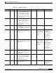
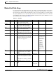

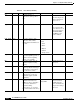
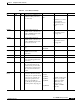
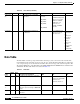
Table Of Contents
- Cisco WAN Modeling Tools User Guide
- Contents
- Related CWM and Switch Documentation
- Obtaining Documentation
- Documentation Feedback
- Cisco Product Security Overview
- Obtaining Technical Assistance
- Obtaining Additional Publications and Information
- Cisco WAN Modeling Tools Overview
- Functionality of the NMT
- Cisco Products Supported by the NMT
- Basic Usage/Charter Functionality
- Gaps
- Data Translation Tools
- System Requirements
- Installing the NMT
- Upgrading the NMT Software
- Starting the NMT
- Removing NMT
- Installing a Cisco WAN Modeling Tools Sub-application
- Removing Sub-applications
- Troubleshooting NMT Installation
- NMT Startup
- NMT Menu Bar
- File Menu
- Display Menu
- Keyboard Commands
- Modeling Processes
- Error Checking
- Troubleshooting NMT
- General Table Information
- Sites Table
- Links Table
- Link Special Cases
- Voice Table
- Data Table
- Bursty Table
- Interface Table
- Feeder Table
- Card Table
- Groups and Network Table
- Nodes Table
- Network Settings
- Model Options
- Feeders
- Obsolete Products
- FastPAD
- Port Concentrator
- Tiered Networks
- Using the Route Command
- AutoRoute
- AutoRoute Least Cost Routing
- PNNI Routing
- Fail Analysis Command
- Build Sites Command
- Optimize Command
- NMT Command Results
- Site Report
- Link Report
- Network Summary Report
- Link Load Report
- ATM & FR Ports Report (or Bursty Data Ports Report)
- Data & Voice Ports Report (or Voice & Data Ports Report)
- Connection Routes Report
- Failed Connections Report
- Parts List Report
- Resource Report/Card Statistics Report
- PNNI Topology Report
- View Summary
- Using the Map Tool
- NMT Map Startup
- Navigating Though a Network View
- Obtaining Link Information - Physical Links
- Obtaining Link Information - Logical Links
- Zooming the Map
- Panning the Map
- Map Color Coding
- Controlling Map Displays in NMT
- NMT Map Main Menu
- Adding New Groups
- Adding Nodes to Existing Groups
- Deleting Groups
- Deleting Nodes or Groups from Existing Groups
- Saving Your Work
- Retrieving Map Data Into NMT
- Using the Map Tool with Fail Analysis
- Using the Map Tool to Analyze Traffic Levels
- Fields Addressed by CET
- Using the CET
- Other CET Commands
- Troubleshooting CET
- Remote CET Extracts
- Translating Between NMT and WANDL Formats
- NMT to Microsoft Excel
- Microsoft Excel to NMT
- Usage Review
- SSI TroubleShooting
- CND PC Import Utilities
- Index

4-11
Cisco WAN Modeling Tools Guide
OL-10426-01, Rev. A0
Chapter 4 Configuration Tables and Fields
Voice Table
Virtual Trunks
The virtual trunking feature introduces the concept of defining multiple trunks within a single trunk port
interface. It was developed to provide connectivity for a hybrid network consisting of Cisco ATM
switches through a public ATM cloud.
NMT models virtual trunks on BNI, BXM, BTM, and AIT ports. Refer to Table 4-5 for information on
virtual trunk configurations.
Voice Table
The Voice Table contains topological information about IGX voice connections in the network. The
important fields in the voice table are the site ends, the type, and the BackCard field. The type defines
the voice compression protocol, and the backcard defines the connection type at the customer's premise.
The primary CWM source of the voice table is the USER_CONN table. The WANDL file for translation is
the demand file. The Voice Table fields are described in Table 4-6.
Table 4-5 Virtual Trunk Configuration
Topic Required Settings Comments
Specifying a Virtual Trunk Links Table
M (Media) field: Enter VT
Trnk_Cd field: Both ends must be
specified. The ends can be different.
VTRate field: Specify the VT rate in
cells per second.
...&Type field: Define the ATM type
of link (ABR, CBR, UBR, VBR, or
leave blank if the links support all
types of traffic).
If the back cards are different, the
maximum size of VT is the
minimum of the two protocols.
Table 4-6 Voice Table
Field Defaults Notes Description and Comments DBF CET TPI
Site 1 – M/H Site name of owner of a
connection.
SITE1 * *
Port ID 1 0 O Logical slot/port number at Site
1 for the connection. Enter 0
and NMT assigns. Enter n.m to
specify port.slot.
ID1 *
Site 2 – M/H Site name of remote end of a
connection.
SITE2 * *
Port ID 2 0 O Logical slot/port number at Site
2 for the connection. Enter 0
and NMT assigns. Enter n.m to
specify port.slot.
ID2 *