
- Cisco WAN Modeling Tools User Guide
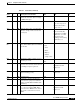
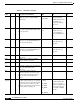
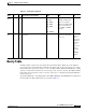
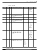
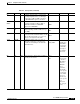
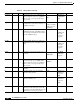
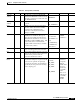
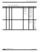
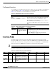
Table Of Contents
- Cisco WAN Modeling Tools User Guide
- Contents
- Related CWM and Switch Documentation
- Obtaining Documentation
- Documentation Feedback
- Cisco Product Security Overview
- Obtaining Technical Assistance
- Obtaining Additional Publications and Information
- Cisco WAN Modeling Tools Overview
- Functionality of the NMT
- Cisco Products Supported by the NMT
- Basic Usage/Charter Functionality
- Gaps
- Data Translation Tools
- System Requirements
- Installing the NMT
- Upgrading the NMT Software
- Starting the NMT
- Removing NMT
- Installing a Cisco WAN Modeling Tools Sub-application
- Removing Sub-applications
- Troubleshooting NMT Installation
- NMT Startup
- NMT Menu Bar
- File Menu
- Display Menu
- Keyboard Commands
- Modeling Processes
- Error Checking
- Troubleshooting NMT
- General Table Information
- Sites Table
- Links Table
- Link Special Cases
- Voice Table
- Data Table
- Bursty Table
- Interface Table
- Feeder Table
- Card Table
- Groups and Network Table
- Nodes Table
- Network Settings
- Model Options
- Feeders
- Obsolete Products
- FastPAD
- Port Concentrator
- Tiered Networks
- Using the Route Command
- AutoRoute
- AutoRoute Least Cost Routing
- PNNI Routing
- Fail Analysis Command
- Build Sites Command
- Optimize Command
- NMT Command Results
- Site Report
- Link Report
- Network Summary Report
- Link Load Report
- ATM & FR Ports Report (or Bursty Data Ports Report)
- Data & Voice Ports Report (or Voice & Data Ports Report)
- Connection Routes Report
- Failed Connections Report
- Parts List Report
- Resource Report/Card Statistics Report
- PNNI Topology Report
- View Summary
- Using the Map Tool
- NMT Map Startup
- Navigating Though a Network View
- Obtaining Link Information - Physical Links
- Obtaining Link Information - Logical Links
- Zooming the Map
- Panning the Map
- Map Color Coding
- Controlling Map Displays in NMT
- NMT Map Main Menu
- Adding New Groups
- Adding Nodes to Existing Groups
- Deleting Groups
- Deleting Nodes or Groups from Existing Groups
- Saving Your Work
- Retrieving Map Data Into NMT
- Using the Map Tool with Fail Analysis
- Using the Map Tool to Analyze Traffic Levels
- Fields Addressed by CET
- Using the CET
- Other CET Commands
- Troubleshooting CET
- Remote CET Extracts
- Translating Between NMT and WANDL Formats
- NMT to Microsoft Excel
- Microsoft Excel to NMT
- Usage Review
- SSI TroubleShooting
- CND PC Import Utilities
- Index

4-15
Cisco WAN Modeling Tools Guide
OL-10426-01, Rev. A0
Chapter 4 Configuration Tables and Fields
Data Table
Port ID
2
0 E Logical slot/port number at the remote
site for the connection. (You can assign
or NMT will assign.)
ID2
Qty 1 M Quantity. Number of data connections.
CONNS *
Since slot and port are
included, this field is
always set to 1.
*
Type 56 E/H Data rate such as 19.2, or 19.2f for fast
EIA (for example, interleaved data and
event bytes).
TYPE *
Derived heuristically.
Modifier F not available
until Release 8.1; nx64,
nx56 shown as the
resulting product starting
with Release 9.1.
*
E2E_TY
PE
SPVC M The end to end type of the connection.
PVC, SPVC, XPVC, Hybred and 1Ended
are all valid.
E2E
Coded:
C - PVC
S- SPVC
H- Hybred
X - XPVC
E - Single ended
EIA 2/2 O Maximum signalling sampling rate, 0 to
20 times per second.
EIA1 /
EIA2
Cd 8 O Encoding format. 7 for 7/8 coded data
and 8 for 8/8 coded data. Connections of
1.344 Mbps or higher require 8/8.
CODE *
Defaults used until
Release 7.2.
PR 0 O Rerouting priority. 0 to 15, with 0 the
highest rerouting priority.
COS
Defaults used prior to
Release 8.5.
*
Ad – O/H Restriction type.
AV D
Red N P Redundancy. Specifies whether data
connections are going to be redundant.
Applies to CDP, SDP, and LDP Y-cable
redundancy.
RED
DFM N O Data Frame Multiplexing.
Y—connection requires DFM. When
connections have DFM, the site value is
ignored. N—connection does not use
DFM.
DFM *
Default used until
Release 7.2.
Table 4-7 Data Table (continued)
Field
Defaul
ts
Note
s Description and Comments DBF CET TPI