
- Cisco WAN Modeling Tools User Guide
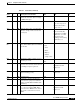
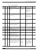
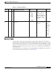
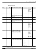
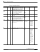
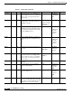
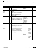
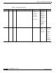
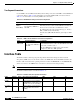
Table Of Contents
- Cisco WAN Modeling Tools User Guide
- Contents
- Related CWM and Switch Documentation
- Obtaining Documentation
- Documentation Feedback
- Cisco Product Security Overview
- Obtaining Technical Assistance
- Obtaining Additional Publications and Information
- Cisco WAN Modeling Tools Overview
- Functionality of the NMT
- Cisco Products Supported by the NMT
- Basic Usage/Charter Functionality
- Gaps
- Data Translation Tools
- System Requirements
- Installing the NMT
- Upgrading the NMT Software
- Starting the NMT
- Removing NMT
- Installing a Cisco WAN Modeling Tools Sub-application
- Removing Sub-applications
- Troubleshooting NMT Installation
- NMT Startup
- NMT Menu Bar
- File Menu
- Display Menu
- Keyboard Commands
- Modeling Processes
- Error Checking
- Troubleshooting NMT
- General Table Information
- Sites Table
- Links Table
- Link Special Cases
- Voice Table
- Data Table
- Bursty Table
- Interface Table
- Feeder Table
- Card Table
- Groups and Network Table
- Nodes Table
- Network Settings
- Model Options
- Feeders
- Obsolete Products
- FastPAD
- Port Concentrator
- Tiered Networks
- Using the Route Command
- AutoRoute
- AutoRoute Least Cost Routing
- PNNI Routing
- Fail Analysis Command
- Build Sites Command
- Optimize Command
- NMT Command Results
- Site Report
- Link Report
- Network Summary Report
- Link Load Report
- ATM & FR Ports Report (or Bursty Data Ports Report)
- Data & Voice Ports Report (or Voice & Data Ports Report)
- Connection Routes Report
- Failed Connections Report
- Parts List Report
- Resource Report/Card Statistics Report
- PNNI Topology Report
- View Summary
- Using the Map Tool
- NMT Map Startup
- Navigating Though a Network View
- Obtaining Link Information - Physical Links
- Obtaining Link Information - Logical Links
- Zooming the Map
- Panning the Map
- Map Color Coding
- Controlling Map Displays in NMT
- NMT Map Main Menu
- Adding New Groups
- Adding Nodes to Existing Groups
- Deleting Groups
- Deleting Nodes or Groups from Existing Groups
- Saving Your Work
- Retrieving Map Data Into NMT
- Using the Map Tool with Fail Analysis
- Using the Map Tool to Analyze Traffic Levels
- Fields Addressed by CET
- Using the CET
- Other CET Commands
- Troubleshooting CET
- Remote CET Extracts
- Translating Between NMT and WANDL Formats
- NMT to Microsoft Excel
- Microsoft Excel to NMT
- Usage Review
- SSI TroubleShooting
- CND PC Import Utilities
- Index

4-18
Cisco WAN Modeling Tools Guide
OL-10426-01, Rev. A0
Chapter 4 Configuration Tables and Fields
Bursty Table
Table 4-8 Bursty Table
Field Defaults Notes Description and Comments DBF CET TPI
Site 1 – M/H Site name of the owner of a connection.
SITE1 *
Master node
unavailable
until 8.1;
assumed to be
Site 1.
*
Port 1 0 E Logical slot/port number at Site 1. (You can
assign, or let NMT automatically assign.)
For multiport channelized cards, the format
is slot.line.port.
ID1 *
Site 2 – M/H Site name of the remote end of a
connection.
SITE2 * *
Port 2 0 E Logical slot/port number at Site 2. (You can
assign, or let NMT automatically assign.)
For multiport channelized cards, the format
is slot.line.port.
ID2 *
Qty 1 M Quantity. Number of data connections.
CONNS *
Since slot,
port, dlci (a
VP1, VC1) are
included,
quantity is
always set at
1.
*
Type VBR M/H Type of connection. Select FR for Frame
Relay, AMT=FR for ATM to Frame,
FR=ATM for Frame Relay to ATM, or
select ABR, CBR, or VBR for ATM
connection.
TYPE *
Until Release
8.2, heuristic
analysis
determined
whether ATM
connections
were ABR,
CBR, or VBR.
*
E2E_TYPE SPVC M The end to end type of the connection.
PVC, SPVC, XPVC, Hybred and 1Ended
are all valid.
E2E
Coded:
C - PVC
S- SPVC
H- Hybred
X - XPVC
E - Single ended