
- Cisco WAN Modeling Tools User Guide
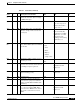
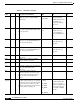
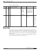
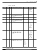
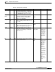
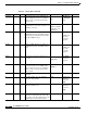
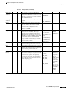
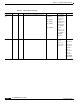
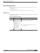
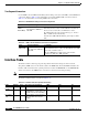
Table Of Contents
- Cisco WAN Modeling Tools User Guide
- Contents
- Related CWM and Switch Documentation
- Obtaining Documentation
- Documentation Feedback
- Cisco Product Security Overview
- Obtaining Technical Assistance
- Obtaining Additional Publications and Information
- Cisco WAN Modeling Tools Overview
- Functionality of the NMT
- Cisco Products Supported by the NMT
- Basic Usage/Charter Functionality
- Gaps
- Data Translation Tools
- System Requirements
- Installing the NMT
- Upgrading the NMT Software
- Starting the NMT
- Removing NMT
- Installing a Cisco WAN Modeling Tools Sub-application
- Removing Sub-applications
- Troubleshooting NMT Installation
- NMT Startup
- NMT Menu Bar
- File Menu
- Display Menu
- Keyboard Commands
- Modeling Processes
- Error Checking
- Troubleshooting NMT
- General Table Information
- Sites Table
- Links Table
- Link Special Cases
- Voice Table
- Data Table
- Bursty Table
- Interface Table
- Feeder Table
- Card Table
- Groups and Network Table
- Nodes Table
- Network Settings
- Model Options
- Feeders
- Obsolete Products
- FastPAD
- Port Concentrator
- Tiered Networks
- Using the Route Command
- AutoRoute
- AutoRoute Least Cost Routing
- PNNI Routing
- Fail Analysis Command
- Build Sites Command
- Optimize Command
- NMT Command Results
- Site Report
- Link Report
- Network Summary Report
- Link Load Report
- ATM & FR Ports Report (or Bursty Data Ports Report)
- Data & Voice Ports Report (or Voice & Data Ports Report)
- Connection Routes Report
- Failed Connections Report
- Parts List Report
- Resource Report/Card Statistics Report
- PNNI Topology Report
- View Summary
- Using the Map Tool
- NMT Map Startup
- Navigating Though a Network View
- Obtaining Link Information - Physical Links
- Obtaining Link Information - Logical Links
- Zooming the Map
- Panning the Map
- Map Color Coding
- Controlling Map Displays in NMT
- NMT Map Main Menu
- Adding New Groups
- Adding Nodes to Existing Groups
- Deleting Groups
- Deleting Nodes or Groups from Existing Groups
- Saving Your Work
- Retrieving Map Data Into NMT
- Using the Map Tool with Fail Analysis
- Using the Map Tool to Analyze Traffic Levels
- Fields Addressed by CET
- Using the CET
- Other CET Commands
- Troubleshooting CET
- Remote CET Extracts
- Translating Between NMT and WANDL Formats
- NMT to Microsoft Excel
- Microsoft Excel to NMT
- Usage Review
- SSI TroubleShooting
- CND PC Import Utilities
- Index
4-24
Cisco WAN Modeling Tools Guide
OL-10426-01, Rev. A0
Chapter 4 Configuration Tables and Fields
Interface Table
Two Segment Connections
Use the NMT to model ATM to Frame Relay interworking connections and ATM to Circuit Emulation
connections. Refer to Table 4-10 for information on modeling ATM and FR connections. Refer to
Table 4-11 for information on modeling ATM to CE connections.
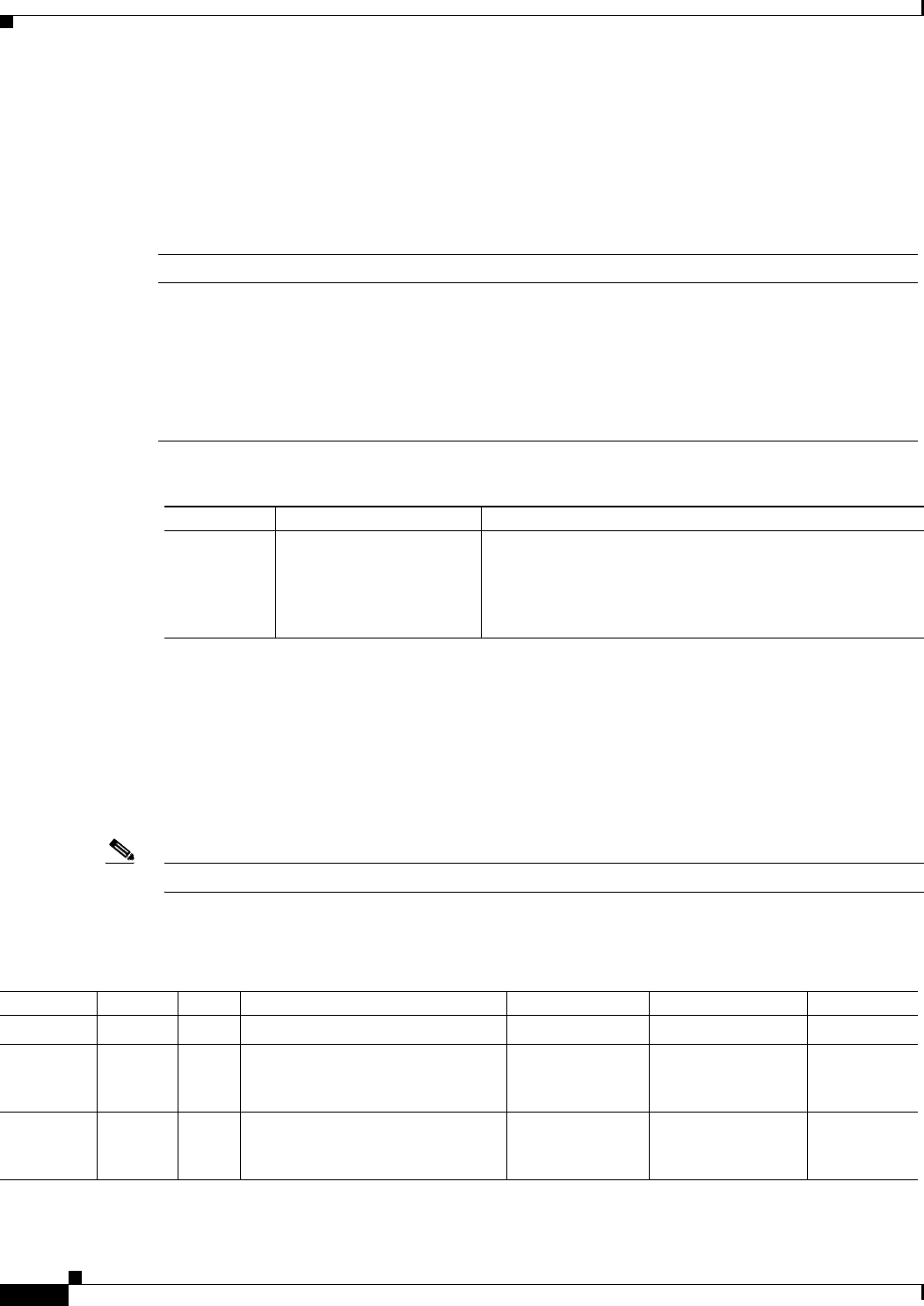
Interface Table
The Interface Table contains topological and partition information about ports in the network.
The primary CWM source for the interface table is the PORT table. For the WANDL translation, the
Interface table is translated into optional parameters in either the BBLINK file or the DEMAND file,
which cross reference the NMT link or connection record based on the slot/port string.
Note The Interface table is called the Port table in the MS Excel and DBF interface.
The Interface Table fields are described in Table 4-12.
Table 4-10 FR ATM Interworking Connection Configuration
Topic Required Settings Comments
Modeling
ATM to
Frame Relay
Bursty Traffic table
Type field: Enter ATM=FR or
FR=ATM.
Use ATM=FR when the ATM interface at Site1 interworks to a
Frame Relay interface at Site2. Use FR=ATM when a Frame Relay
interface at Site1 to interworks to an ATM interface at Site2.
The ATM end must support the specified traffic type (i.e., must be a
BPX or an IGX with 8.2.5 functionality).
All traffic values (MIR, PIR, FR=ATM) are given in kbps for ATM
traffic
Table 4-11 ATM to Circuit Emulation Connection Configuration
Topic Required Settings Comments
Modeling
ATM to CE
Bursty Traffic table
Type field: Enter ATM=CE or
CE=ATM.
Use ATM=CE when the ATM interface at Site1 interworks to a
Circuit Emulation interface at Site2. Use CE=ATM when the ATM
end is at Site 2 and CE is at Site 1.
All values (MIR,PIR) are in Kbps and the circuit should be
configured as a CBR where MIR equals PIR.
Table 4-12 Interface Table (Port Specific Parameters)
Field Defaults Notes Description and Comments DBF CET TPI
Site – M/H Site name.
SITE * *
PortID 0 O Slot/port address used for linking
the NMTs Bursty traffic table to the
port table. Also used for bundling.
HUBID *
FeederPort
_ID
0 E Slot/port address (cross reference)
in the port table. Also used for
bundling.
FDR_ID *