
- Cisco WAN Modeling Tools User Guide
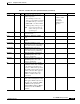
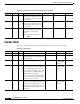
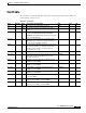
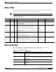

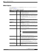
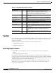
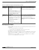
Table Of Contents
- Cisco WAN Modeling Tools User Guide
- Contents
- Related CWM and Switch Documentation
- Obtaining Documentation
- Documentation Feedback
- Cisco Product Security Overview
- Obtaining Technical Assistance
- Obtaining Additional Publications and Information
- Cisco WAN Modeling Tools Overview
- Functionality of the NMT
- Cisco Products Supported by the NMT
- Basic Usage/Charter Functionality
- Gaps
- Data Translation Tools
- System Requirements
- Installing the NMT
- Upgrading the NMT Software
- Starting the NMT
- Removing NMT
- Installing a Cisco WAN Modeling Tools Sub-application
- Removing Sub-applications
- Troubleshooting NMT Installation
- NMT Startup
- NMT Menu Bar
- File Menu
- Display Menu
- Keyboard Commands
- Modeling Processes
- Error Checking
- Troubleshooting NMT
- General Table Information
- Sites Table
- Links Table
- Link Special Cases
- Voice Table
- Data Table
- Bursty Table
- Interface Table
- Feeder Table
- Card Table
- Groups and Network Table
- Nodes Table
- Network Settings
- Model Options
- Feeders
- Obsolete Products
- FastPAD
- Port Concentrator
- Tiered Networks
- Using the Route Command
- AutoRoute
- AutoRoute Least Cost Routing
- PNNI Routing
- Fail Analysis Command
- Build Sites Command
- Optimize Command
- NMT Command Results
- Site Report
- Link Report
- Network Summary Report
- Link Load Report
- ATM & FR Ports Report (or Bursty Data Ports Report)
- Data & Voice Ports Report (or Voice & Data Ports Report)
- Connection Routes Report
- Failed Connections Report
- Parts List Report
- Resource Report/Card Statistics Report
- PNNI Topology Report
- View Summary
- Using the Map Tool
- NMT Map Startup
- Navigating Though a Network View
- Obtaining Link Information - Physical Links
- Obtaining Link Information - Logical Links
- Zooming the Map
- Panning the Map
- Map Color Coding
- Controlling Map Displays in NMT
- NMT Map Main Menu
- Adding New Groups
- Adding Nodes to Existing Groups
- Deleting Groups
- Deleting Nodes or Groups from Existing Groups
- Saving Your Work
- Retrieving Map Data Into NMT
- Using the Map Tool with Fail Analysis
- Using the Map Tool to Analyze Traffic Levels
- Fields Addressed by CET
- Using the CET
- Other CET Commands
- Troubleshooting CET
- Remote CET Extracts
- Translating Between NMT and WANDL Formats
- NMT to Microsoft Excel
- Microsoft Excel to NMT
- Usage Review
- SSI TroubleShooting
- CND PC Import Utilities
- Index

4-25
Cisco WAN Modeling Tools Guide
OL-10426-01, Rev. A0
Chapter 4 Configuration Tables and Fields
Interface Table
Speed 0 O/H Clock speed of the access port.
Values range from
• 56 to 2048 kbps for frame relay
• 3622 to 38336 for ATM on an AUSM
on an MGX 8220 edge concentrator.
• 80000, 96000, or 353208 for ATM on
a BPX, depending on the type of port
Note
A port speed of 0 has no
effect on the speed of the
specified port.
SPEED *
Limitation: Older
devices, the
MC3810 and
FastPAD are not
supported.
*
Iftype 0 O Interface Type. Applies to MPSM
connections only.
IF *
Lines 0 O Number of T1/E1 lines in IMA
port.
IMA_L *
Frame O Number of ATM cells in IMA
Frame.
IMA_F *
EngMinBw 0 O Minimum Cell Rate in egress
(transmit) direction for the partition.
Zero value means no partitioning.
EGR_MIN_BW
EngMaxBw 0 O Maximum Cell rate in egress
(transmit) direction for the partition.
Zero value means no partitioning.
EGR_MAX_BW
MinLCN 0 O Minimum number of channels in
the PNNI partition. Zero value
means no partitioning.
MIN_LCN
MaxLCN 0 O Maximum number of channels in
the PNNI partition. Zero value
means no partitioning.
MAX_LCN
BF 0 O Booking Factor used to calculate
committed cell rate that contributes
to the interface load. Ranges are
from 1% to 200%. If 0 is specified,
the globally assigned value is used
for this connection. This applies to
PNNI connections only, and is
similar to %Util for Autoroute
connections.
BF
Partition 0 Specification of the partition that
most of the remaining fields in this
table apply to. Blank entry refers to
the whole port. AutoRoute, PNNI,
or MPLS can be specified. If
multiple MPLS partitions, MPLS2
can be used for the 2nd MPLS
partition.
PART
Table 4-12 Interface Table (Port Specific Parameters) (continued)
Field Defaults Notes Description and Comments DBF CET TPI