
- Cisco WAN Modeling Tools User Guide
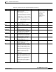
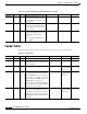
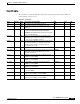
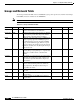
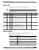
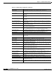
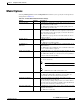
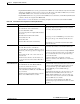
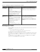
Table Of Contents
- Cisco WAN Modeling Tools User Guide
- Contents
- Related CWM and Switch Documentation
- Obtaining Documentation
- Documentation Feedback
- Cisco Product Security Overview
- Obtaining Technical Assistance
- Obtaining Additional Publications and Information
- Cisco WAN Modeling Tools Overview
- Functionality of the NMT
- Cisco Products Supported by the NMT
- Basic Usage/Charter Functionality
- Gaps
- Data Translation Tools
- System Requirements
- Installing the NMT
- Upgrading the NMT Software
- Starting the NMT
- Removing NMT
- Installing a Cisco WAN Modeling Tools Sub-application
- Removing Sub-applications
- Troubleshooting NMT Installation
- NMT Startup
- NMT Menu Bar
- File Menu
- Display Menu
- Keyboard Commands
- Modeling Processes
- Error Checking
- Troubleshooting NMT
- General Table Information
- Sites Table
- Links Table
- Link Special Cases
- Voice Table
- Data Table
- Bursty Table
- Interface Table
- Feeder Table
- Card Table
- Groups and Network Table
- Nodes Table
- Network Settings
- Model Options
- Feeders
- Obsolete Products
- FastPAD
- Port Concentrator
- Tiered Networks
- Using the Route Command
- AutoRoute
- AutoRoute Least Cost Routing
- PNNI Routing
- Fail Analysis Command
- Build Sites Command
- Optimize Command
- NMT Command Results
- Site Report
- Link Report
- Network Summary Report
- Link Load Report
- ATM & FR Ports Report (or Bursty Data Ports Report)
- Data & Voice Ports Report (or Voice & Data Ports Report)
- Connection Routes Report
- Failed Connections Report
- Parts List Report
- Resource Report/Card Statistics Report
- PNNI Topology Report
- View Summary
- Using the Map Tool
- NMT Map Startup
- Navigating Though a Network View
- Obtaining Link Information - Physical Links
- Obtaining Link Information - Logical Links
- Zooming the Map
- Panning the Map
- Map Color Coding
- Controlling Map Displays in NMT
- NMT Map Main Menu
- Adding New Groups
- Adding Nodes to Existing Groups
- Deleting Groups
- Deleting Nodes or Groups from Existing Groups
- Saving Your Work
- Retrieving Map Data Into NMT
- Using the Map Tool with Fail Analysis
- Using the Map Tool to Analyze Traffic Levels
- Fields Addressed by CET
- Using the CET
- Other CET Commands
- Troubleshooting CET
- Remote CET Extracts
- Translating Between NMT and WANDL Formats
- NMT to Microsoft Excel
- Microsoft Excel to NMT
- Usage Review
- SSI TroubleShooting
- CND PC Import Utilities
- Index
4-30
Cisco WAN Modeling Tools Guide
OL-10426-01, Rev. A0
Chapter 4 Configuration Tables and Fields
Network Settings
P Delay Limit Maximum delay (in ms) that can be sustained for this connection type.
A Delay Limit Maximum delay (in ms) that can be sustained for this connection type, if
applicable.
NTS Delay Limit Maximum delay (in ms) that can be sustained for this connection type, if
applicable.
CVM-CVM Delay Limit Maximum delay (in ms) that can be sustained for this connection type, if
applicable.
Voice Combine Timeout Timeout (units * 0.125 ms) to combine fast packets to cell for voice connections.
Range is 0-255.
TS Data Combine Timeout Timeout (units * 0.125 ms) to combine fast packets to cell for time stamped data
connections. Range is 0-255.
NTS Data Combine Timeout Timeout (units * 0.125 ms) to combine fast packets to cell for non time stamped
data connections. Range is 0-255.
Link Booking Factor For PNNI, the global booking factor to be applied to all PNNI link ports. Range is
from 1 to 200. Individual ports can be specified using the Interface Table.
Line Booking Factor For PNNI, the global booking factor to be applied to all PNNI line ports. Range is
from 1 to 200. Individual ports can be specified using the Interface Table.
CAC Algorithm For PNNI, which Connection Admission Control Algorithm to use.
CTD for CBR Cell Transfer Delay for CBR class of service in microseconds.
CTD for VBR Cell Transfer Delay for VBR class of service, both real time and non real time, in
microseconds.
CDV for CBR Cell Delay Variation for CBR class of service in microseconds.
CDV for VBR Cell Delay Variation for VBR class of service in microseconds.
CLR for CBR Cell Loss Ratio for CBR class of service. Enter integer N, where N is an exponent
of 10**(-N). Range is 6 through 10.
CLR for VBR Cell Loss Ratio for VBR class of service. Enter integer N, where N is an exponent
of 10**(-N). Range is 6 through 10.
AvCR Prop. Multiplier For PNNI, used in the algorithm to determine significant change of link AvCR.
Expressed as a percentage, range is 1-99
AvCR Minimum Threshold For PNNI, used in the algorithm to determine significant change of link AvCR.
Expressed as a percentage, range is 1-99
CTD Prop. Multiplier For PNNI, this proportional multiplier is used to determine significant change of
link cell transfer delay. Expressed as a percentage, range is 1-99
CDV Prop. Multiplier For PNNI, this proportional multiplier is used to determine significant change of
link cell delay variation. Expressed as a percentage, range is 1-99
Equal Path Epsilon The connection can only be routed using a restricted media. A satellite link, for
instance.
Load Balancing Rule For PNNI, used if an alternate path exists for a given connection
On-Demand Routing Rule For PNNI, defines the algorithm of calculating route for on-demand route request
Link Selection Rule For PNNI, defines the sorting order of horizontal parallel links between two nodes
from the same peer group.
Maximum Crankbacks For PNNI, maximum number of crankbacks allowed on the routing node. Range is
1-5
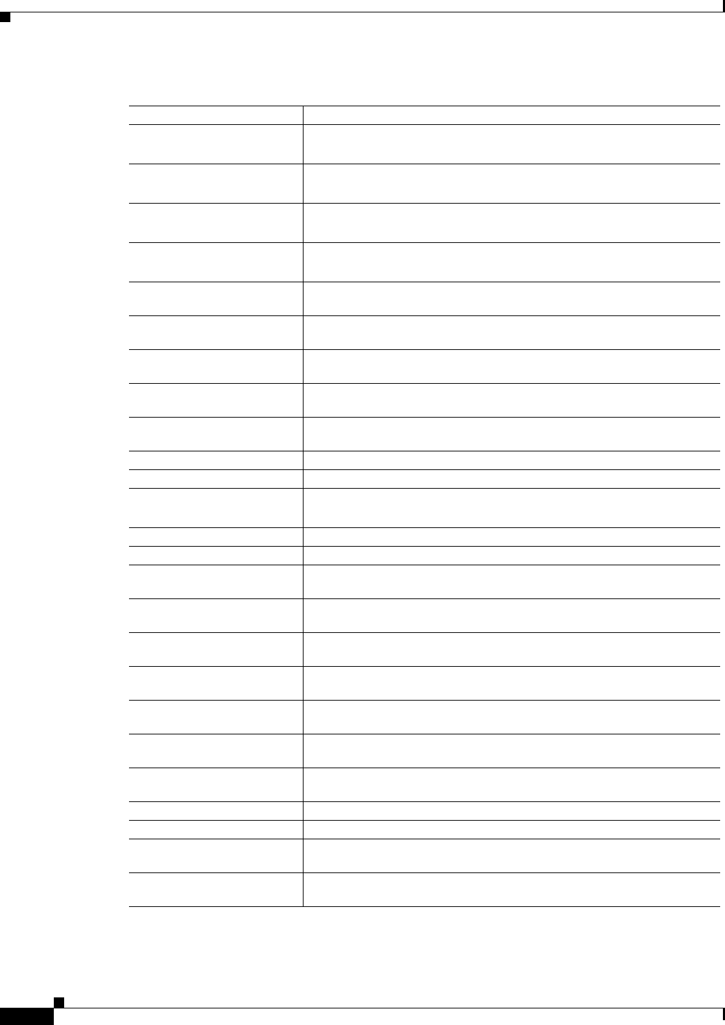
Table 4-17 Model Setting Configuration (continued)
Parameter Modeling Effect