
- Cisco WAN Modeling Tools User Guide
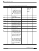
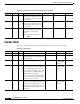
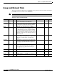
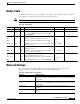
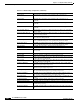
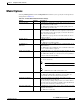
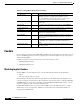
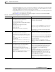
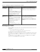
Table Of Contents
- Cisco WAN Modeling Tools User Guide
- Contents
- Related CWM and Switch Documentation
- Obtaining Documentation
- Documentation Feedback
- Cisco Product Security Overview
- Obtaining Technical Assistance
- Obtaining Additional Publications and Information
- Cisco WAN Modeling Tools Overview
- Functionality of the NMT
- Cisco Products Supported by the NMT
- Basic Usage/Charter Functionality
- Gaps
- Data Translation Tools
- System Requirements
- Installing the NMT
- Upgrading the NMT Software
- Starting the NMT
- Removing NMT
- Installing a Cisco WAN Modeling Tools Sub-application
- Removing Sub-applications
- Troubleshooting NMT Installation
- NMT Startup
- NMT Menu Bar
- File Menu
- Display Menu
- Keyboard Commands
- Modeling Processes
- Error Checking
- Troubleshooting NMT
- General Table Information
- Sites Table
- Links Table
- Link Special Cases
- Voice Table
- Data Table
- Bursty Table
- Interface Table
- Feeder Table
- Card Table
- Groups and Network Table
- Nodes Table
- Network Settings
- Model Options
- Feeders
- Obsolete Products
- FastPAD
- Port Concentrator
- Tiered Networks
- Using the Route Command
- AutoRoute
- AutoRoute Least Cost Routing
- PNNI Routing
- Fail Analysis Command
- Build Sites Command
- Optimize Command
- NMT Command Results
- Site Report
- Link Report
- Network Summary Report
- Link Load Report
- ATM & FR Ports Report (or Bursty Data Ports Report)
- Data & Voice Ports Report (or Voice & Data Ports Report)
- Connection Routes Report
- Failed Connections Report
- Parts List Report
- Resource Report/Card Statistics Report
- PNNI Topology Report
- View Summary
- Using the Map Tool
- NMT Map Startup
- Navigating Though a Network View
- Obtaining Link Information - Physical Links
- Obtaining Link Information - Logical Links
- Zooming the Map
- Panning the Map
- Map Color Coding
- Controlling Map Displays in NMT
- NMT Map Main Menu
- Adding New Groups
- Adding Nodes to Existing Groups
- Deleting Groups
- Deleting Nodes or Groups from Existing Groups
- Saving Your Work
- Retrieving Map Data Into NMT
- Using the Map Tool with Fail Analysis
- Using the Map Tool to Analyze Traffic Levels
- Fields Addressed by CET
- Using the CET
- Other CET Commands
- Troubleshooting CET
- Remote CET Extracts
- Translating Between NMT and WANDL Formats
- NMT to Microsoft Excel
- Microsoft Excel to NMT
- Usage Review
- SSI TroubleShooting
- CND PC Import Utilities
- Index

4-32
Cisco WAN Modeling Tools Guide
OL-10426-01, Rev. A0
Chapter 4 Configuration Tables and Fields
Feeders
Feeders
Specify all feeder equipment in the MGX, IGX, and IPX products explicitly in the Sites table. You can
also use the NMT to provision feeders as required by the connection demand. You can even provision
additional routing IGXs.
Implicit and explicit feeder generation is discussed in the following sections:
• Modeling Implicit Feeders
• Modeling Explicit Feeders
Modeling Implicit Feeders
To allow NMT to generate implicit feeders, enter the following information into the Site Table:
• hub site
• link connecting the hub to the feeder
Enter information about both the hub and feeder interfaces in the Traffic tables. For implicit feeders,
connection endpoints are the hub nodes. The actual feeder ends cannot be referenced directly. IGX, IPX,
and MGX8820 feeder nodes can be implicitly generated by NMT. The MGX 8850, if used as a feeder,
must be an explicit feeder.It can not be an implicit feeder.
Implicit IGX and IPX feeders are generated when a BPX is used as the hub node for Voice or Data
Traffic. They are also generated when a BPX is used as the hub node for Frame Relay Traffic not
designated for an MGX 8220.
Share Redundancy YY—non-redundant connections can share cards that are used on
redundant connections, essentially getting redundancy for free.
If no, non-redundant connections cannot share these cards, and are
provisioned by a separate non-redundant service module.
Reserve pkt/swt NY
—hold a packet switch in reserve for the VDP background test of
standby cards.
Adavtive VAD NY—all voice connections will be treated as they are in the PROTECT
state.
Use Time Stamp Queue YY
—then low speed data connections on LDP and SDP cards will be used
Bundle Parts YY
—provision bundled parts when possible in the parts list.
FR Route Choice YY
—route FR connections for optimal bandwidth usage. If N, route FR
connections for optimal performance.
Priority Bumping NY—use the priority bumping algorithm for re-routing of connections.
Connections with higher COS can bump lower priority connections in
order to reroute.
Model PNNI RCC & SSC YY
—automatically create and provision the PNNI signalling connections;
the PNNI Hello Protocol (RCC) and the PNNI Signalling Protocol
(SSC).
Special Settings Menu N Add two new menus which enable you to alter internal parameters of
basic Cisco products.
Table 4-18 Execute Menu Model Parameter Settings
Setting Defaults Description