
- Cisco WAN Modeling Tools User Guide
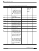
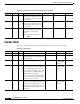
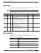
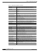
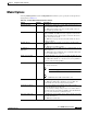
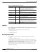
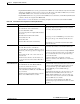
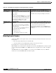
Table Of Contents
- Cisco WAN Modeling Tools User Guide
- Contents
- Related CWM and Switch Documentation
- Obtaining Documentation
- Documentation Feedback
- Cisco Product Security Overview
- Obtaining Technical Assistance
- Obtaining Additional Publications and Information
- Cisco WAN Modeling Tools Overview
- Functionality of the NMT
- Cisco Products Supported by the NMT
- Basic Usage/Charter Functionality
- Gaps
- Data Translation Tools
- System Requirements
- Installing the NMT
- Upgrading the NMT Software
- Starting the NMT
- Removing NMT
- Installing a Cisco WAN Modeling Tools Sub-application
- Removing Sub-applications
- Troubleshooting NMT Installation
- NMT Startup
- NMT Menu Bar
- File Menu
- Display Menu
- Keyboard Commands
- Modeling Processes
- Error Checking
- Troubleshooting NMT
- General Table Information
- Sites Table
- Links Table
- Link Special Cases
- Voice Table
- Data Table
- Bursty Table
- Interface Table
- Feeder Table
- Card Table
- Groups and Network Table
- Nodes Table
- Network Settings
- Model Options
- Feeders
- Obsolete Products
- FastPAD
- Port Concentrator
- Tiered Networks
- Using the Route Command
- AutoRoute
- AutoRoute Least Cost Routing
- PNNI Routing
- Fail Analysis Command
- Build Sites Command
- Optimize Command
- NMT Command Results
- Site Report
- Link Report
- Network Summary Report
- Link Load Report
- ATM & FR Ports Report (or Bursty Data Ports Report)
- Data & Voice Ports Report (or Voice & Data Ports Report)
- Connection Routes Report
- Failed Connections Report
- Parts List Report
- Resource Report/Card Statistics Report
- PNNI Topology Report
- View Summary
- Using the Map Tool
- NMT Map Startup
- Navigating Though a Network View
- Obtaining Link Information - Physical Links
- Obtaining Link Information - Logical Links
- Zooming the Map
- Panning the Map
- Map Color Coding
- Controlling Map Displays in NMT
- NMT Map Main Menu
- Adding New Groups
- Adding Nodes to Existing Groups
- Deleting Groups
- Deleting Nodes or Groups from Existing Groups
- Saving Your Work
- Retrieving Map Data Into NMT
- Using the Map Tool with Fail Analysis
- Using the Map Tool to Analyze Traffic Levels
- Fields Addressed by CET
- Using the CET
- Other CET Commands
- Troubleshooting CET
- Remote CET Extracts
- Translating Between NMT and WANDL Formats
- NMT to Microsoft Excel
- Microsoft Excel to NMT
- Usage Review
- SSI TroubleShooting
- CND PC Import Utilities
- Index

4-33
Cisco WAN Modeling Tools Guide
OL-10426-01, Rev. A0
Chapter 4 Configuration Tables and Fields
Feeders
Implicit IGX and IPX feeders can be generated when an IGX is used as the hub, but only when the traffic
demands on the IGX exceed the resources of one node. Therefore, if the hub is an IGX, and you want to
design IGX or IPX feeders, it is better to make the feeders explicit.
Implicit MGX 8820 feeders are generated when a BPX is used as a hub node, and the Bursty Traffic table
contains connections designated for MGX 8220.
Refer to Table 4-19 for information on modeling an implicit feeder tiered network with the NMT.
Table 4-19 Tiered Network Configurations with Implicit Feeders
Topic Required Settings Comments
IPX/IGX Feeders Sites table
Site field: Enter the name of the hub node
Type field: Enter BPX or IGX.
Tiered feeder flag: Enter Y if implicit IPX should be a
tiered feeder.
IGX field: Enter N for IPX and Y for IGX.
BC field: Enter T3 or E3.
FC field: Enter AIT.
RLC field: Enter Y for trunk card redundancy.
Only IGX and BPX can be used as hubs. An IGX hub will
only generate implicit feeders when the resources required
exceed those allowed by an IGX.
Specify type of feeder for BPX/IGX type of site in the Sites
table; specify the type of the link between hub and feeder.
The redundancy of feeder links is determined by the RLC
field in the Sites table.
Voice, Data, or Bursty Traffic tables
Site fields: Enter the name of the hub node
Type field: Enter any valid IGX or IPX Voice, Data, or
Frame Relay connection type (that is not supported on
BPX.)
BC field: Enter T1, E1, V, X, or other valid voice or
data back cards.
Fdr BC field: Leave blank or enter line interface for
access feeder such as Port Concentrator, MC3810, or
FastPAD.
Voice and data connections on IPX or IGX tiered network
feeders may only terminate on another IPX or IGX feeder.
Hub IDs and feeder IDs are not defined for implicit IPX/IGX
feeders. To specify the physical location of feeder trunks and
lines, you must make the feeder node explicit by having it
appear in the Sites table.
In the Bursty Traffic table, verify that the connection
originates or terminates on the IPX feeder as a Frame Relay
connection.
MGX 8220 Feeders:
General Instructions
Bursty Traffic table
Site field: Enter the site name. Must be BPX site.
Type field: any from the list of choices.
BC (Back Card) field: Enter the back card that
connects the BPX to the BNM card on the MGX 8220
edge concentrator.
Fdr BC (Feeder Back Card) field: Enter the customer
interface on the MGX 8220 service module.
MGX 8220 edge concentrators are provisioned from the BC
and Fdr BC fields in the Bursty Traffic table. If the back card
specified can support MGX 8220, and the feeder back card
can support the traffic type with an MGX 8220 service
module, NMT will provision an MGX 8220 edge
concentrators.
The Fdr BC field determines the connection interface to the
MGX 8220 feeder. The NMT determines the front card
(FRSM, AUSM or CESM), based on the feeder back card
selected. If T3 is selected as the feeder back card, the NMT
assigns as SRM-3T3 service module.
If connection type implies AUSM card, the PCR value
determines the port speed and whether more than one T1/E1
is required.