
- Cisco WAN Modeling Tools User Guide
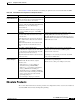
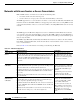
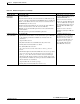
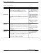
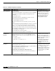
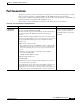
Table Of Contents
- Cisco WAN Modeling Tools User Guide
- Contents
- Related CWM and Switch Documentation
- Obtaining Documentation
- Documentation Feedback
- Cisco Product Security Overview
- Obtaining Technical Assistance
- Obtaining Additional Publications and Information
- Cisco WAN Modeling Tools Overview
- Functionality of the NMT
- Cisco Products Supported by the NMT
- Basic Usage/Charter Functionality
- Gaps
- Data Translation Tools
- System Requirements
- Installing the NMT
- Upgrading the NMT Software
- Starting the NMT
- Removing NMT
- Installing a Cisco WAN Modeling Tools Sub-application
- Removing Sub-applications
- Troubleshooting NMT Installation
- NMT Startup
- NMT Menu Bar
- File Menu
- Display Menu
- Keyboard Commands
- Modeling Processes
- Error Checking
- Troubleshooting NMT
- General Table Information
- Sites Table
- Links Table
- Link Special Cases
- Voice Table
- Data Table
- Bursty Table
- Interface Table
- Feeder Table
- Card Table
- Groups and Network Table
- Nodes Table
- Network Settings
- Model Options
- Feeders
- Obsolete Products
- FastPAD
- Port Concentrator
- Tiered Networks
- Using the Route Command
- AutoRoute
- AutoRoute Least Cost Routing
- PNNI Routing
- Fail Analysis Command
- Build Sites Command
- Optimize Command
- NMT Command Results
- Site Report
- Link Report
- Network Summary Report
- Link Load Report
- ATM & FR Ports Report (or Bursty Data Ports Report)
- Data & Voice Ports Report (or Voice & Data Ports Report)
- Connection Routes Report
- Failed Connections Report
- Parts List Report
- Resource Report/Card Statistics Report
- PNNI Topology Report
- View Summary
- Using the Map Tool
- NMT Map Startup
- Navigating Though a Network View
- Obtaining Link Information - Physical Links
- Obtaining Link Information - Logical Links
- Zooming the Map
- Panning the Map
- Map Color Coding
- Controlling Map Displays in NMT
- NMT Map Main Menu
- Adding New Groups
- Adding Nodes to Existing Groups
- Deleting Groups
- Deleting Nodes or Groups from Existing Groups
- Saving Your Work
- Retrieving Map Data Into NMT
- Using the Map Tool with Fail Analysis
- Using the Map Tool to Analyze Traffic Levels
- Fields Addressed by CET
- Using the CET
- Other CET Commands
- Troubleshooting CET
- Remote CET Extracts
- Translating Between NMT and WANDL Formats
- NMT to Microsoft Excel
- Microsoft Excel to NMT
- Usage Review
- SSI TroubleShooting
- CND PC Import Utilities
- Index

4-40
Cisco WAN Modeling Tools Guide
OL-10426-01, Rev. A0
Chapter 4 Configuration Tables and Fields
FastPAD
Setting Up Switched
Voice Con ne ctions
Voice Traffic table
Connect the FastPADs:
• Quantity field: Set the number of connections between a pair of FastPADs
to the estimated peak number of simultaneous calls between the two
destinations.
• Type field: Enter Session.
• BC (Back Card) field: Select valid FTC back card (V, X, T1, or E1).
• Fdr BC (Feeder Back Card) field: Leave blank.
Create dummy FastPAD connections:
• Site 1, Site 2 fields. Connect a site entered above to itself, e.g., Boston,
Boston
• Hub ID fields. Optional. Hub 1 ID and Hub 2 ID can be used to specify the
slot port of each end of the connection. Connect a site entered above to
itself, e.g., 8.1, 8.1. This connection is intersect, intracard, and interport.
• Quantity field: The number of dummy connections should equal one half
the peak number of simultaneous calls expected between the FastPAD and
all other switched voice destinations.
• Type field: Enter the voice traffic speed type.
• Fdr BC (Feeder Back Card) field: Enter V for the VFC-03 card.
To add FastPAD switched voice
connections, i.e., voice connections
between at least one voice card on a
FastPAD connected to at least one
voice card on many FastPADs, you
must perform a two-step process:
connect the FastPADs and add
dummy FastPAD connections.
Setting Up Multiple
FastPADs at the
Same Site
Data Traffic table, Voice Traffic table, Bursty Traffic table
• Hub ID field: The ID is given to the port of the FTC/FTM card on the
IPX/IGX switch that connects to the specific FastPAD. ID values can be
— Port only: 0
— Slot and port: mm.nn
Where mm = 1 to 32 and nn = 1 to 31
For connections between multiple
FastPADs at a site or to associate
specific connections with specific
FastPADs, use the Hub ID field for all
FastPAD connections that originate or
terminate at that site.
All connections associated with one
specific FastPAD should have the
same Hub ID throughout the three
traffic tables.
Changing Default
Parameters
Feeders table
• Hub ID field: Enter Slot.Port (e.g., 6.4).
• Type field: Enter FP-4 for a FastPAD Micro, FP-8 for a regular FastPAD, or
FP to have the NMT determine which one to use.
• Speed field: Enter the speed you want.
Data Traffic table, Voice Traffic table, Bursty Traffic table
• Hub1 ID field: Enter the Hub ID value entered in the Feeders table (e.g.,
6.4).
• Hub 2 ID field: Enter the Hub ID for the appropriate site.
You can specify a FastPAD or
FastPAD micro unit and can specify
the maximum speed of the composite
link, i.e., 64 kbps, 128, kbps, or
256 kbps. If you specify FP (a generic
FastPAD), NMT chooses the best one.
If you specify 0 as the speed, NMT
picks the best one.
Table 4-22 FastPAD Configuration (continued)
Topic Required Settings Comments