
- Cisco WAN Modeling Tools User Guide
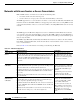
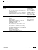
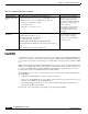
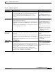
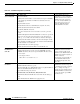
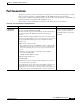
Table Of Contents
- Cisco WAN Modeling Tools User Guide
- Contents
- Related CWM and Switch Documentation
- Obtaining Documentation
- Documentation Feedback
- Cisco Product Security Overview
- Obtaining Technical Assistance
- Obtaining Additional Publications and Information
- Cisco WAN Modeling Tools Overview
- Functionality of the NMT
- Cisco Products Supported by the NMT
- Basic Usage/Charter Functionality
- Gaps
- Data Translation Tools
- System Requirements
- Installing the NMT
- Upgrading the NMT Software
- Starting the NMT
- Removing NMT
- Installing a Cisco WAN Modeling Tools Sub-application
- Removing Sub-applications
- Troubleshooting NMT Installation
- NMT Startup
- NMT Menu Bar
- File Menu
- Display Menu
- Keyboard Commands
- Modeling Processes
- Error Checking
- Troubleshooting NMT
- General Table Information
- Sites Table
- Links Table
- Link Special Cases
- Voice Table
- Data Table
- Bursty Table
- Interface Table
- Feeder Table
- Card Table
- Groups and Network Table
- Nodes Table
- Network Settings
- Model Options
- Feeders
- Obsolete Products
- FastPAD
- Port Concentrator
- Tiered Networks
- Using the Route Command
- AutoRoute
- AutoRoute Least Cost Routing
- PNNI Routing
- Fail Analysis Command
- Build Sites Command
- Optimize Command
- NMT Command Results
- Site Report
- Link Report
- Network Summary Report
- Link Load Report
- ATM & FR Ports Report (or Bursty Data Ports Report)
- Data & Voice Ports Report (or Voice & Data Ports Report)
- Connection Routes Report
- Failed Connections Report
- Parts List Report
- Resource Report/Card Statistics Report
- PNNI Topology Report
- View Summary
- Using the Map Tool
- NMT Map Startup
- Navigating Though a Network View
- Obtaining Link Information - Physical Links
- Obtaining Link Information - Logical Links
- Zooming the Map
- Panning the Map
- Map Color Coding
- Controlling Map Displays in NMT
- NMT Map Main Menu
- Adding New Groups
- Adding Nodes to Existing Groups
- Deleting Groups
- Deleting Nodes or Groups from Existing Groups
- Saving Your Work
- Retrieving Map Data Into NMT
- Using the Map Tool with Fail Analysis
- Using the Map Tool to Analyze Traffic Levels
- Fields Addressed by CET
- Using the CET
- Other CET Commands
- Troubleshooting CET
- Remote CET Extracts
- Translating Between NMT and WANDL Formats
- NMT to Microsoft Excel
- Microsoft Excel to NMT
- Usage Review
- SSI TroubleShooting
- CND PC Import Utilities
- Index

4-41
Cisco WAN Modeling Tools Guide
OL-10426-01, Rev. A0
Chapter 4 Configuration Tables and Fields
Port Concentrator
Port Concentrator
The Port Concentrator provides a method for concentrating voice and data connection types as a Frame
Relay connection extending to an FTC or FRM card. The NMT models and provisions Port
Concentrators so that they support Frame Relay connections. The card is modeled as a 44-port FRP card,
with the PC interface being optional but defaulting to V35.
Refer to Table 4-23 for information on modeling a network that uses port concentrators.
Table 4-23 Port Concentrator Configuration Notes
Topic Required Settings Comments
Instructing the NMT
to Design Port
Concentrators
Bursty table
Type field: Select FR, ATM=FR, or FR=ATM.
BC (back card) field: To specify a PC termination, enter PC in the BC field of
the site that has the PC. The NMT rejects PC if the connection type is
incorrect.
Fdr BC (feeder back card) field: Each PC termination can also specify which
PC interface is required. Enter V (for V.35), V1 (for V.11) or V2 (for V.28) in
the corresponding Fdr I/F field. If you leave the field blank, the interface
defaults to V.35.
Hub ID (for Site 1 and Site 2) fields
• The port ID is the slot.port ID for an FRP-PC card and is a virtual port. The
virtual port range is from 1 to 44, where ports 1 to 11 are on physical port 1,
12 to 22 are on physical port 2, 23 to 33 are on port 3, and 34 to 44 are on
port 4.
• Hub IDs can be used to model over-subscription, port-to-multiport
connections, and multiple PCs.
• A hub ID of 0 allows NMT to do design.
FdrID (Feeder ID) field: Not used
Access Ports table
Hub ID field: Slot is the PC slot and port is the virtual port (1 to 44). Do not
use feeder slot or feeder port column.
Speed field: Enter the port speed. If not supported, it will be rounded up to the
nearest supported speed. Speeds 9, 14, 19, and 38 will be respectively
interpreted as 9.6, 14.4, 19.2, and 38.4. If you have an Access Port table entry
for a PC port, the port speed is determined by the connections assigned to it.
NMT designs port concentrators if,
and only if, you enter connections that
have port concentrator terminations.
Geis bundling format is not supported
for FRP-PC.