
- Cisco WAN Modeling Tools User Guide
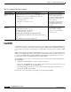
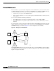
Table Of Contents
- Cisco WAN Modeling Tools User Guide
- Contents
- Related CWM and Switch Documentation
- Obtaining Documentation
- Documentation Feedback
- Cisco Product Security Overview
- Obtaining Technical Assistance
- Obtaining Additional Publications and Information
- Cisco WAN Modeling Tools Overview
- Functionality of the NMT
- Cisco Products Supported by the NMT
- Basic Usage/Charter Functionality
- Gaps
- Data Translation Tools
- System Requirements
- Installing the NMT
- Upgrading the NMT Software
- Starting the NMT
- Removing NMT
- Installing a Cisco WAN Modeling Tools Sub-application
- Removing Sub-applications
- Troubleshooting NMT Installation
- NMT Startup
- NMT Menu Bar
- File Menu
- Display Menu
- Keyboard Commands
- Modeling Processes
- Error Checking
- Troubleshooting NMT
- General Table Information
- Sites Table
- Links Table
- Link Special Cases
- Voice Table
- Data Table
- Bursty Table
- Interface Table
- Feeder Table
- Card Table
- Groups and Network Table
- Nodes Table
- Network Settings
- Model Options
- Feeders
- Obsolete Products
- FastPAD
- Port Concentrator
- Tiered Networks
- Using the Route Command
- AutoRoute
- AutoRoute Least Cost Routing
- PNNI Routing
- Fail Analysis Command
- Build Sites Command
- Optimize Command
- NMT Command Results
- Site Report
- Link Report
- Network Summary Report
- Link Load Report
- ATM & FR Ports Report (or Bursty Data Ports Report)
- Data & Voice Ports Report (or Voice & Data Ports Report)
- Connection Routes Report
- Failed Connections Report
- Parts List Report
- Resource Report/Card Statistics Report
- PNNI Topology Report
- View Summary
- Using the Map Tool
- NMT Map Startup
- Navigating Though a Network View
- Obtaining Link Information - Physical Links
- Obtaining Link Information - Logical Links
- Zooming the Map
- Panning the Map
- Map Color Coding
- Controlling Map Displays in NMT
- NMT Map Main Menu
- Adding New Groups
- Adding Nodes to Existing Groups
- Deleting Groups
- Deleting Nodes or Groups from Existing Groups
- Saving Your Work
- Retrieving Map Data Into NMT
- Using the Map Tool with Fail Analysis
- Using the Map Tool to Analyze Traffic Levels
- Fields Addressed by CET
- Using the CET
- Other CET Commands
- Troubleshooting CET
- Remote CET Extracts
- Translating Between NMT and WANDL Formats
- NMT to Microsoft Excel
- Microsoft Excel to NMT
- Usage Review
- SSI TroubleShooting
- CND PC Import Utilities
- Index
4-42
Cisco WAN Modeling Tools Guide
OL-10426-01, Rev. A0
Chapter 4 Configuration Tables and Fields
Tiered Networks
Tiered Networks
Tiered networks are a special network configuration of Cisco WAN switches. A tiered network consists
of a BPX or IGX hub node linked to a maximum of 16 IPX/IGX nodes or MGX 8220/ MGX 8850 edge
concentrators designated as feeder nodes. A feeder node provides the following features:
• It expands the port capacity of the BPX/IGX switch
• It has no routing capabilities, so it is not counted against the maximum number of switches allowed
in the network.
Use a feeder node under the following circumstances:
• when a BPX switch does not support a required line interface, such as T1/E1/V35/X21
• when a BPX switch does not provide required network services, such as Frame Relay or circuit
emulation.
In a tiered network, each feeder has only one link to the hub node. In the NMT, tiered network generation
is driven by the type and the line interface of the connection for creating IPX/IGX feeders and MGX
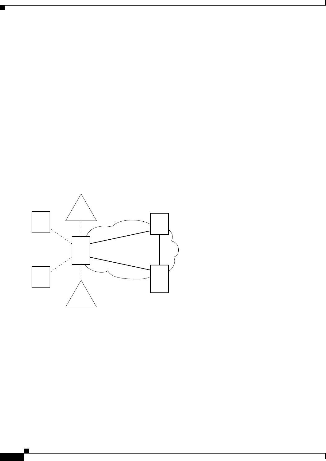
8220/MGX 8850 edge concentrators. Figure 4-2 shows an example of a tiered network.
Figure 4-2 Example of a Tiered Network
If an IPX/IGX/MGX8220 feeder is not in the Sites table, but is generated by NMT, it is called an implicit
feeder. When the node is in the Sites table, it is called an explicit feeder. The requirements for modeling
implicit and explicit feeders differ.
MGX
8220
Shelf
IGX
BPX
Paris
Belgium
London
MGX
8220
Shelf
IPX
IPX
BPX
S6042